2
\$\begingroup\$

I am designing a monitoring circuit for a battery powered device that is charged from a solar panel. The circuit uses an LM339 to indicate the input voltages via two dual colour LEDs, one for the battery voltage and one for the solar panel voltage. The LEDs will be red to indicate low voltage, orange (both LEDs on) to represent a mid range voltage, and green to show a high voltage. Each comparator input contains a potentiometer to allow for calibration and adjustment of the transition points as desired. See the schematic below. enter image description here
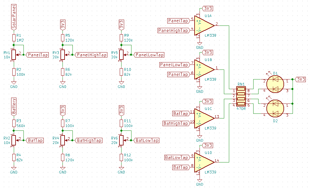
After building and testing the circuit I have observed some very strange behaviour from the LM339. The two comparator elements being used for the solar panel monitoring (A & B) work fine and the transitions on the outputs occur at the correct points for the input voltages, however the comparators being used for the battery (C & D) do not change their outputs at the correct voltage.

The solar panel and battery resistor dividers are adjusted to produce 2.048V at their maximum expected voltage and the other trimpots are set arbitrarily for now. The input conditions for the output transition points for each comparator are summarised below. These are only rough measurements but it's pretty obvious that U1C and U1D aren't even close to being correct.

    U1A    U1B    U1C    U1D
V+  1.499  1.506  2.071  1.64
V-  1.506  1.501  1.909  1.775

I have tried powering the LM339 from 5V instead to get all of the inputs within the common mode range (Vcc - 1.5) but this made no significant difference. I also tried using an LMV339 which has a wider common mode voltage range (Vcc - 0.7V) and this is also exhibiting the same behaviour.

Why would two of the comparators in the LM339 exhibit this incorrect behaviour while the other two work fine, when all of them have identical input topologies?

Any help would be appreciated.

Edit: As per the suggestions I have improved the ground connection and bypassing, decreased the resistors by about a factor of 10, and added 1µF caps on each of the taps. This has made no significant difference. enter image description here
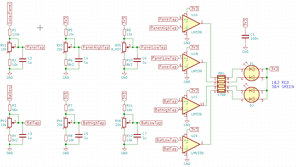
Here are my new test results for the point at which each comparator transitions.

    U1A    U1B    U1C    U1D
V+  1.163  1.159  2.084  1.646
V-  1.154  1.168  1.918  1.790
\$\endgroup\$
8
  • \$\begingroup\$ Did you compare input offset from bias current and voltage vs worst case spec? Is there noise? \$\endgroup\$
    – D.A.S.
    Commented Aug 16, 2018 at 2:48
  • \$\begingroup\$ Is this all done on a breadboard, right? \$\endgroup\$ Commented Aug 16, 2018 at 4:25
  • \$\begingroup\$ @TonyEErocketscientist I haven't tried to measure bias current/voltage. Offset voltage shouldn't be big enough to have a significant effect. Bias current may have some influence since current through the resistor dividers is between 10-20µA compared to worst case of 400nA for the LMV339. But would the different elements in the one chip really be that different. There is only very minor high frequency noise present that is hard to quantify on the old analogue scope that I have access to. \$\endgroup\$
    – Donald B
    Commented Aug 16, 2018 at 5:07
  • \$\begingroup\$ @AliChen No I'm testing it on a prototype of the actual PCB. \$\endgroup\$
    – Donald B
    Commented Aug 16, 2018 at 5:08
  • 1
    \$\begingroup\$ Is there any chance that your PCB ground is weak? And why you don't have any explicit hysteresis? It could be they are ringing at frequency above your scope bandwidth. Your reference tap dividers are made out of unreasonably large resistors, I would make them about 10k-10k, and put a 1uF on each of them. The power rail also is lacking a bypass cap. So ... \$\endgroup\$ Commented Aug 16, 2018 at 7:04

1 Answer 1

0
\$\begingroup\$

Well I feel silly now. I've found the problem. My prototype PCB had the wrong two pins on the pots shorted so I had cut the traces and shorted the wiper across to the other pin. Due to the way the board was laid out the BatTap and PanelTap are run from different places and I didn't realise that BatTap was now connected to the wrong pin of the pot after the mod. So the voltage I was measuring for BatTap was not actually what the LMV339 was getting. What led me to the solution was wondering if there was a poor connection on the BatTap line that was causing increased resistance in that line.

\$\endgroup\$

Your Answer

By clicking “Post Your Answer”, you agree to our terms of service and acknowledge you have read our privacy policy.

Not the answer you're looking for? Browse other questions tagged or ask your own question.