1
\$\begingroup\$

I went to http://www.elm-chan.org/docs/lcd/hd44780_e.html in an attempt to find out how to make an LCD module work with the shortest timings. While the site does help with the initialization of the LCD, I feel as if it is not helping me enough.

Various sources state that for each LCD command or data processed, there is roughly a 40uS to 1.7mS delay before the command is complete.

The website mentions that I could poll the busy flag on the LCD but that would be too long of a delay (Its mentioned under the CPU load heading on the site).

So what I want to do is create a fixed delay in software so that the software continues to function even if the LCD gets disconnected from the circuit during operation.

The question is, where exactly do I implement the long microsecond delay in the code?

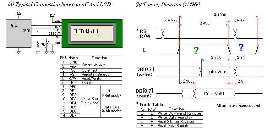
Do I insert the delay after I set enable to high (where green question mark is) or do I insert the delay after I set enable to low (where blue question mark is)?

I think its the latter, but I want to make sure.

LCD timing

\$\endgroup\$
1
  • 1
    \$\begingroup\$ For most operations you need both, before and after. And for some operations you need at least 1.52 ms \$\endgroup\$
    – Maple
    Commented Sep 20, 2018 at 21:47

2 Answers 2

0
\$\begingroup\$

You should be looking at the datasheet for the LCD module, not at a typical application.

Anywhere the datasheet says you must meet a minimum delay time you need to make sure that you meet that delay. For the example timing diagram you provide, it looks like enable must be high for at least 450ns and its period must be at least 1000ns. You also need to make sure you meet the setup and hold times for R/S, RW, and DATA. Depending on how fast your processor can toggle a GPIO line you may need several short delays in the software.

\$\endgroup\$
1
  • \$\begingroup\$ I should be able to meet minimum delays easy. I'm using an AT89S52 with a 20Mhz crystal attached, so each instruction will execute at 0.54uS minimum, so if anything I could get away with a couple nop's \$\endgroup\$ Commented Sep 21, 2018 at 3:09
-1
\$\begingroup\$

Various sources state that for each LCD command or data processed, there is roughly a 40uS to 1.7mS delay before the command is complete.

The question is, where exactly do I implement the long microsecond delay in the code?

The HD44780 and its clones will read the data/command in when the Enable (E) pin goes from high to low. That is the way you tell the LCD to process the command. The 1 millisecond delay should be there. That's essentially the blue question mark period.

\$\endgroup\$

Your Answer

By clicking “Post Your Answer”, you agree to our terms of service and acknowledge you have read our privacy policy.

Not the answer you're looking for? Browse other questions tagged or ask your own question.