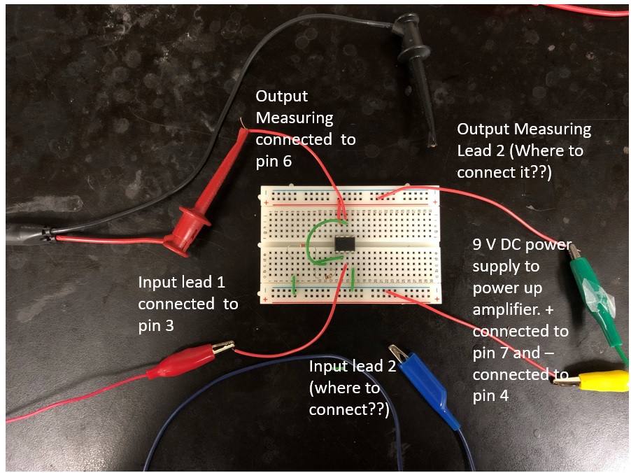
I am trying to build an amplifier using op amp 741. But I am failing to build it on breadboard.
I am connecting the positive end of a 9 V battery to pin 7 and negative end to pin 4. As per my knowledge and instructions available all over the internet. Pin 3 is to be connected with the input. The voltage source that I want to amplify has two leads coming out of it positive and negative. If I connect positive lead of my input to pin 3, where should I connect the negative lead??
Similarly, while measuring the amplified output from pin 6 what should be the other point of reference.
I am need of a circuit fix.
I am attaching the pic of the amplifier connections here. Your help will be really appreciated.
\$\begingroup\$
\$\endgroup\$
2
-
\$\begingroup\$ Ties in with reasons not to use an op-amp with a breadboard. \$\endgroup\$– user105652Commented Oct 6, 2018 at 1:45
-
\$\begingroup\$ and you've made an error with the bottom-left green wire - the bottom end isn't connected to anything. \$\endgroup\$– brhansCommented Oct 6, 2018 at 1:47
Add a comment
|
1 Answer
\$\begingroup\$
\$\endgroup\$
4
An op-amp is a building block of a working amplifier. It's not what you want in and of itself.
Here's the short story:
- Use two 9V batteries, for a +9V supply and a -9V supply. You don't have to run "ground" to the op-amp, although you can, depending on the circuit.
- Read this page. I can't recommend it very strongly -- it's in the top five things that popped up when I searched for "differential amplifier". But it should give you some guidance about what to do with your op-amp in the circuit.
- Using a 741 op-amp is like using a Model T Ford. They're interesting antiques, nice to have in a museum, but you wouldn't want to use one every day. There are much better op-amps these days. There were much better op-amps 30 years ago. I doubt that 741's are finding their way into new designs by anyone other than hobbyists.
-
2\$\begingroup\$ "You don't have to run "ground" to the op-amp," Ack! You most certainly do. The common battery terminal MUST be connected to signal ground. \$\endgroup\$ Commented Oct 6, 2018 at 3:03
-
\$\begingroup\$ @WhatRoughBeast I think what is being suggested is that a bipolar +9V/-9V supply is used so that -9V is connected to the op amp instead of ground. Yes, the common terminal must be connected to signal ground, but not to the op amp itself. \$\endgroup\$ Commented Oct 6, 2018 at 13:21
-
\$\begingroup\$ @WhatRoughBeast: This picture in the Wikipedia article about op-amp applications. Ground is not connected to any pin of the op-amp. This isn't oddball -- this is typical. It is a hugely common error by op-amp beginners to think that ground must be run to some pin on the op-amp -- instead, it rarely should. \$\endgroup\$ Commented Oct 6, 2018 at 14:25
-
\$\begingroup\$ @WhatRoughBeast. Eh, no coffee yet, the above was poorly stated. A list: the afore-mentioned difference amplifier circuit; no ground connections. Positive-gain amplifiers; no ground connections. Negative-gain amplifiers using an amp with bias current; + input to ground through a resistor. Single-supply circuits: connections referenced to "virtual ground", not the actual negative rail. You have to reference ground somehow, but you often don't connect directly to ground, which is what the OP seemed to think. \$\endgroup\$ Commented Oct 6, 2018 at 14:34
