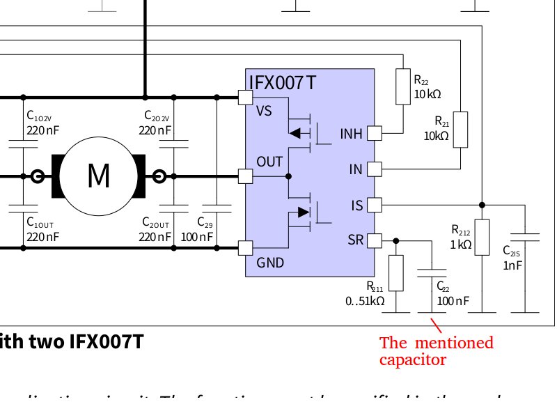
I am designing a simple 3-phase inverter for BLDC Motor control. For that purpose, i plan to use a IFX007T from Infineon. The slew rate is controlled via a resistance connected in series to SR pin.
I do not understand how this resistance is used to adjust the slew rate but i suppose the analog magic behind it far too complex and beyond the scope of this question. What i would like to know is: What is the purpose of the capacitor connected parallel to this resistance in the reference design? As far as I know, its a decoupling capacitor that basically sends any high frequency components to GND.
The reason I am asking is; in older versions of this H-Bridge such as BTN7930 there is only the resistance connected to the SR pin and no caps what so ever. Since I am a little tight on space, I wonder if it would be alright to omit it with IFX007T.

