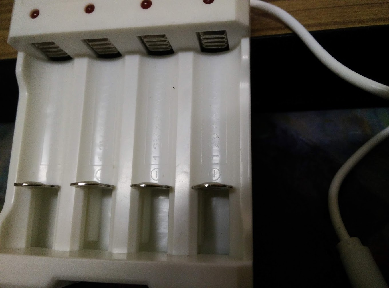
If you know how (simple) this charger is, there is no surprise that you measure 5 V and the 5 V is totally expected. Also there is no "intelligence" going on in this charger, the circuit is as basic as it can get and will be very similar to this:

simulate this circuit – Schematic created using CircuitLab
If the battery is removed and you use a voltmeter (which has a very high resistance) almost no current (about 0.5 uA) flows so almost no voltage (theoretically 7.5 uV) will drop across R1. So basically there will be 5 V across the battery terminals when there is no battery connected.
When you do place a battery it will have a voltage of around 1.2 V, that will give about 5 V - 1.2 V = 3.8 V across R1 so about 3.8 V / 15 ohms = 0.25 A will flow and that will charge the battery. When the battery is full there might be 1.4 V across it and that will decrease the charging current only slightly to 0.24 A.
That 0.24 A when fully charged will make your batteries warm up a bit, it is then better to remove them from the charger!
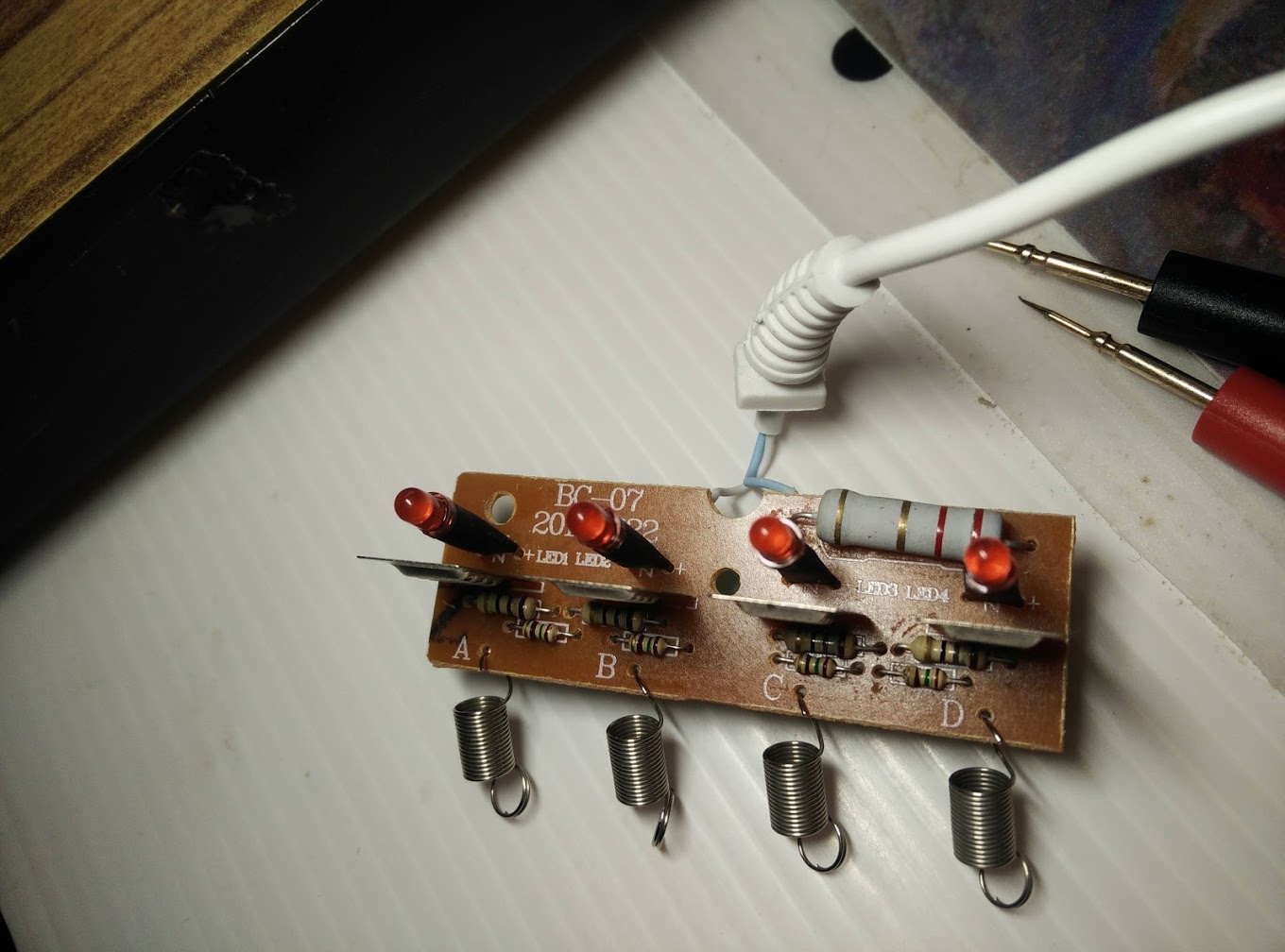
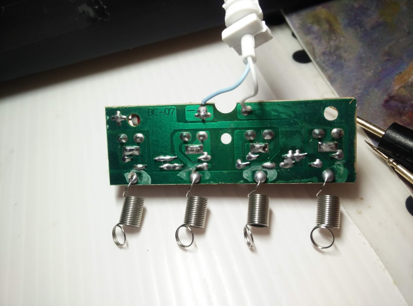
Edit: after you added photos from the charger's PCB we can see that there is a large (2.2 ohm?) resistor and it is shared by all the charging circuits. It does not change much to the principle of operation of this charger.


