1
\$\begingroup\$

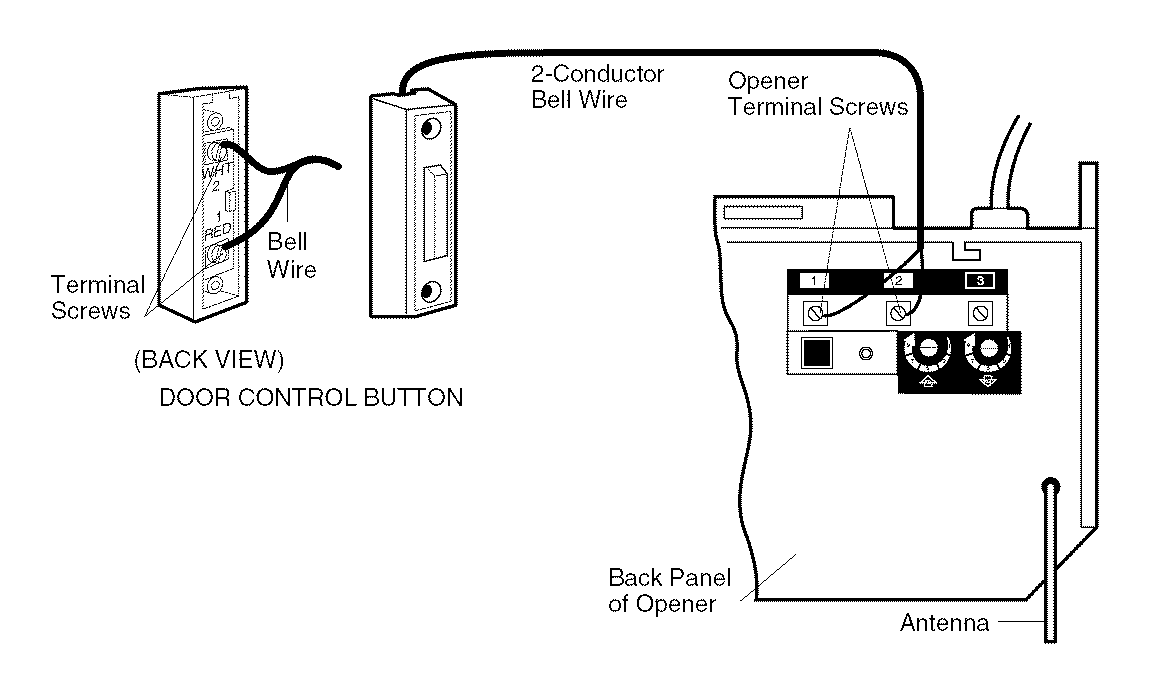
I am attempting to use my Raspberry Pi's GPIO to activate a garage door opener (specifically Craftsman 139.5364812). As far as I can tell, the garage door is operated by shorting two terminal screws together (see page 17 of the manual), resulting in about 20-30 mA between them.

enter image description here

I'm trying to measure the voltages involved here with a simple home multimeter.

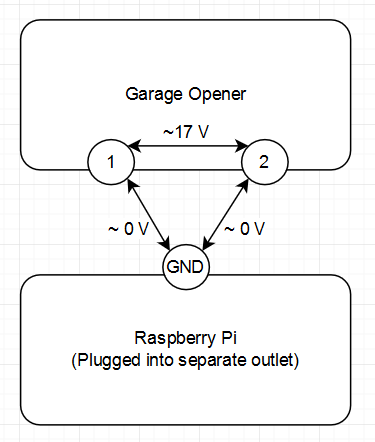
The voltage between the garage opener's red (1) and white (2) terminal screws is 17-18 volts.

However, then I plugged in my Pi into a separate wall plug, and measured the voltage between the Pi's GROUND pin and the garage opener's terminal screws. For both screws, the difference from Pi GND to screw was 0 volts.

enter image description here

How is this situation possible? Am I missing anything obvious? This has been tested with two different multimeters.

\$\endgroup\$
6
  • 2
    \$\begingroup\$ It's not a gnd , just a floating node. By definition Gnd is 0V and low impedance \$\endgroup\$
    – D.A.S.
    Commented Jan 4, 2019 at 1:57
  • 4
    \$\begingroup\$ pick up any battery, 1.5V AA for instance ..... do not connect it to anything ..... measure the voltage between the arduino and either of the battery contacts ..... what do you get? \$\endgroup\$
    – jsotola
    Commented Jan 4, 2019 at 2:02
  • 1
    \$\begingroup\$ Realistically, without reliable knowledge of the circuitry behind the switch, you'll want to use a small relay. \$\endgroup\$ Commented Jan 4, 2019 at 2:04
  • \$\begingroup\$ @jsotola ~0 volts between the battery terminal and Pi ground, for both terminals. So I'm guessing that shows the issue lies in my understanding of voltage, not in the garage-opener circuit? :) \$\endgroup\$
    – nbura
    Commented Jan 4, 2019 at 2:09
  • 1
    \$\begingroup\$ you could try an optocoupler like 4N35, a relay will work, the 4N35 might work, \$\endgroup\$ Commented Jan 4, 2019 at 4:13

3 Answers 3

1
\$\begingroup\$

Those two circuits are isolated from each other. Either the Pi, the garage door opener, or (most likely) both have no galvanic connection to Gnd and/or neutral.

Thus the multimeter simply connects the isolated systems together through its internal impedance. As there cannot be any current flow between the systems, no potential can be maintained across the multimeter impedance.

\$\endgroup\$
1
\$\begingroup\$

Voltmeters work by creating a closed circuit. For example, when you place the probes on the terminals of a battery, the voltage produce by the battery cause a current to flow in one probe, through the voltmeter, back out the other probe, and back into the battery. This is a closed loop and the electrons are literally recycled in this loop and renergized by the battery. The voltmeter measures the current with a fixed resistor and can determine the voltage using V=IR. If the current is 0 then the measured voltage will be 0, according to the equation.

So, I have two separate batteries, one being a 1.5v battery and the other being a 9v battery. The batteries are in no way connected. If I placed one probe on the + terminal of the 9v battery and the other probe on the - terminal of the 1.5v battery, what will I measure? There is no closed loop, so no current, therefore no voltage is measured. This is basically what you did with your two circuits. The batteries need to be connected somehow before you can measure a voltage.

Get a few batteries out and test this yourself. Only when you have a closed loop will you measure a voltage potential. Depending on how you connect the batteries and probes, you can measure positive and negative 0v, 1.5v, 7.5v, 9v, and 10.5v. For further learning, I recommend the app EveryCircuit so you can think up and simulate circuits on you phone.

In practice, this problem is usually solved by connecting all the ground pins together. If you connect the GND pin on the Raspberry Pi to the GND on the garage circuit, then you would see the results you expected because everything is sharing the same reference (ground). However, this can cause noise issues, can be unsafe to lower voltage electronics downstream if something failed, and will blow your circuit if you do it wrong. This is why others in the comments have suggested optocouplers or relays. This protects the low voltage (sensitive) electronics from high voltage or high power electronics like motors. If a relay, which uses both the high and low voltages, is crushed or otherwise fails, it is very unlike if not impossible to short and send the high voltage energy into the low voltage electronics. However, if a mosfet or IC that’s using the high/low voltages suddenly fails, it will behave unexpectedly and may pass the high voltage down to the low voltage electronics and cause everything to fail. Depending on your setup, this can be very expensive and/or very dangerous.

\$\endgroup\$
1
\$\begingroup\$

Previous answers are too complicated, there is the simple explanation:

Either the PI or the Garage door, or perhaps both uses isolated power supply. Most appliance uses isolated power supply for safety reason and this is why you have no "common ground".

To solve it, just run a wire between the Pi GND and the garage door GND.

\$\endgroup\$

Your Answer

By clicking “Post Your Answer”, you agree to our terms of service and acknowledge you have read our privacy policy.

Not the answer you're looking for? Browse other questions tagged or ask your own question.