Okay so I have two questions. I am looking at a schematic diagram of a remote control for a toy car and I can't seem to figure out what the "n/o" and "n/c" components stand for that are attached to the motor supply. Also not sure if they are the same component or they just have different looks. My other questions is what is the RL1 component with the swirls and the two lines?
-
5\$\begingroup\$ It says RELAY under the RL1 symbol. Even if that wasn't there, the iron core inductor symbol (the inductor symbol with the two lines) next to the switches should give you a hint as to what it is. What type of mechanical switch is usually activated from magnetic activity? \$\endgroup\$– user103380Commented Jan 24, 2019 at 15:32
-
\$\begingroup\$ @KingDuken usually one draws a dashed line between the coil and the switch though, so that the components can't be thought separate, though. \$\endgroup\$– John DvorakCommented Jan 25, 2019 at 19:26
3 Answers
RL1 is a relay, a type of electrically-actuated mechanical switch. The swirls are the relay's coil, and the two lines indicate that it's wrapped around a magnetic core.
The thing labelled N/O and N/C is also part of the relay; N/O is "normally open", which means that switch contact is open, or disconnected, when the relay coil is not energized. N/C likewise is "normally closed", which means that switch contact is closed, i.e. connected, when the relay coil is not energized. When a current is flowing through the relay coil, the magnetic field it creates pulls the switch over, opening the NC contact and closing the NO one.
Note that in the context of integrated circuits you may see "NC" used to mean "not connected", but here with it being next to a relay's contacts it's pretty unambiguous.
-
5\$\begingroup\$ Technically here, NC means both normally closed and not connected 😃 \$\endgroup\$– PasserbyCommented Jan 24, 2019 at 15:30
-
3\$\begingroup\$ @Passerby That's true! But it's pretty clear that normally closed is the intended reading. \$\endgroup\$– HearthCommented Jan 24, 2019 at 15:31
-
1\$\begingroup\$ And just for completeness, N/O and N/C are used for any mechanical switch, not just electrically-actuated ones. You'll also see them on toggle switches, for example. \$\endgroup\$ Commented Jan 25, 2019 at 14:25
NO = normally open contact
NC = normally closed contact
Normally open (NO) contacts connect the circuit when the relay is activated; the circuit is disconnected when the relay is inactive. Normally closed (NC) contacts disconnect the circuit when the relay is activated; the circuit is connected when the relay is inactive. All of the contact forms involve combinations of NO and NC connections.
-
\$\begingroup\$ NC and NO can also be used with switches, in addition to relays, with the same meanings. In this situation they are shown on a relay. \$\endgroup\$– StoborCommented Jan 25, 2019 at 3:50
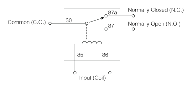
N.O. and N.C. stand for normally open and normally closed contacts. These are connections that are part of a relay (or relay like components, ex. Solid state relays or modules). They are not independant parts. As the name implies, normally open contacts will be open, or not connected to the common pin, when the relay is off.
RL1 is the relay which the NO and NC pins are part of. The swirly lines is the inductor, the electromagnetic wire wound core that is used to make the relay work. This diagram shows it more clearly as a single unit.

You can use a Single pole single Throw relay which will only have a normally open contact (normally closed SPST relays do exist too), or a Single pole double throw relay which will have both. Other variations of relays exist with multiple combinations of NC and NO contacts.
-
1\$\begingroup\$ It may be worth noting that with a relay symbol like the one you show, N.C. and N.O will not usually be labeled, but the symbol will be drawn as though the energizing the coil will move the switch toward it. In the OP's schematic, the NC and NO labels were needed because for whatever reason the switch was drawn moving sideways with respect to the coil. \$\endgroup\$– supercatCommented Jan 24, 2019 at 17:33
-
1\$\begingroup\$ @supercat I believe the convention is also that the symbol is drawn so that the switch is in its de-energized state, even if it's shown sideways. \$\endgroup\$– HearthCommented Jan 24, 2019 at 21:20

