0
\$\begingroup\$

I have found a basic design for a surge protection device (SPD), and I would like to simplify it. However, I have little experience designing SPD circuits.

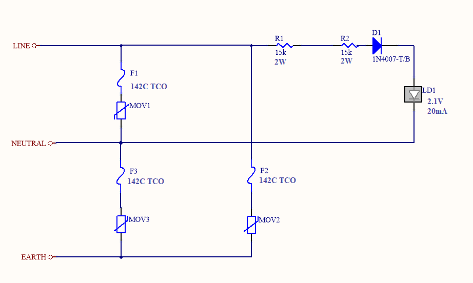
This is my parallel type SPD circuit with embedded LED indicator:

Circuit

In this case:

  • Can I remove MOV3 and TCO F3 between N and E? Will this still comply with IEC61643-11/UL 1449?
  • Do I have to add a normal fuse (5A) at the input side of the parallel type? I will add it for the serial type but not sure for parallel.
  • I will make a direct contact between TCO and MOV on my PCB. This system will be inside in epoxy. How will this affect the thermal performace? (I know, this is an experimental question.)
  • I've chosen a 10 kA surge MOV for 10 kA protection level. Should I overrate the MOV as you would overrate a fuse i.e. using a 5 A fuse for 3 A normal current?
\$\endgroup\$
4
  • 1
    \$\begingroup\$ SPD ? Is that the Social Democratic Party of Germany or Symphysis pubis dysfunction ? But looking at the schematic you probably mean some sort of surge protector. It does not hurt to write SPD in full once so that its clear what you mean. I would add a small signal diode (1N4148) in (anti-) parallel with the LED so that the LED will never suffer more than 0.6 V reverse voltage. LEDs don't like reverse voltages. Yes the 1N4007 will block it also but there will always be some leakage. \$\endgroup\$ Commented Feb 6, 2019 at 8:21
  • \$\begingroup\$ Please take time to review spelling, punctuation, grammar, and conciseness. Asking a well-formatted and structured question is the key to getting a quality answer. \$\endgroup\$
    – andowt
    Commented Feb 6, 2019 at 8:31
  • \$\begingroup\$ SPD is defined in the title. \$\endgroup\$
    – AnalogKid
    Commented Feb 6, 2019 at 13:41
  • \$\begingroup\$ 4.9 years ago. . . \$\endgroup\$
    – AnalogKid
    Commented Jan 1 at 2:51

2 Answers 2

1
\$\begingroup\$

The MOVs to earth probably violate UL 1449, anyway.

I would strongly suggest purchasing a copy and reading it in detail; it's a bit of a slog, reading standards, but it is the primary source. It would be foolish to take random answers on the internet at their word, when it comes to something as important as product safety!

On that note: I wasn't able to find a copy of it to prepare this answer, so consider this hearsay and apocrypha. The safety-related discussion is however motivated by standards such as IEC 60950-1, which I have read. The mains wiring is common knowledge, and also reflected in various standards and codes.


Most often, a GDT is used, in series with the earth connection to the pair of MOVs, to eliminate ground leakage current.

A GDT is not used, alone, because once ignited by a surge, it can continue to conduct, when neutral-earth voltage is present.

High neutral can occur in two situations: swapped lines (unpolarized or incorrectly wired outlets), and both-lines-high environments. North America residential 240V is 120-0-120V with respect to earth (both hot), and commercial/industrial circuits can also be 208V or 240V line-to-line (three phase). It is not a good assumption to assume neutral is always near earth.

Note that much equipment gets by without common-mode surge protection, by merely handling the voltage with sufficient isolation. 2.5kV is a typical rating; it's given by the CAT(egory) rating of the equipment.

Without specifications for what you're protecting, or what standards you aim to meet, I'm afraid there isn't much to be said about your circuit, nor transformations of it.

Here is one article illustrating a simplification:
A circuit simplification for AC power supply surge protection devices | EDN
however, note that they do not test a high-neutral condition, which as mentioned, can result in a fault or hazardous condition.

\$\endgroup\$
-1
\$\begingroup\$

Generally surges couple well with capacitive transformers so that you don’t use resistor power dividers. This improves the protection after the 1st surge when the fuse blows for the MOV drawing excessive current. (Research Offline Power Supplies)

There are many solutions but the best design has all the specs tolerances on input voltage Power lightning transient test levels and output V,I,P, then current limiting without fused MOV’s may be avoided.

The ideal is to divide the voltage with film caps then raise the impedance (and attenuate HF surge impulses ) into a ferrite L to rectify with a full wave diode bridge to get 2f instead of 1/2 wave f flicker then into a cap shunt to reduce the ripple. This way fuses are optional using a series R as a fuse if you expect 50% overvoltage in your region but even this can be protected.

See examples of this here. E.g. 330nF film to 100uF e-cap is a 3300:1 voltage divider for AC It is not quite linear with the diode bridge effects, so simulate the link above and optimize your inputs and outputs with extra LEDs up to whatever Vdc you like.

Your 30kohm 5W +5W to LED of 15 Ohms is 2000:1 voltage divider.

One can optimize the design for 20Vdc out with a string of LEDs at 20mA by changing component values in Falstad with 350Vp 50Hz or whatever you like. This way you can avoid two 5W resistors.

I chose to offer a better design instead critiquing a worse design. If you understand something good. if you want more info ask for what you need.

\$\endgroup\$

Your Answer

By clicking “Post Your Answer”, you agree to our terms of service and acknowledge you have read our privacy policy.

Not the answer you're looking for? Browse other questions tagged or ask your own question.