1
\$\begingroup\$

I am new in the automation industry, and now I am focusing on learning how to wire correctly analog inputs in detail, since last time I tried I damaged the module input because of wrong wiring. Here I have several questions about analog input wiring. They may seem pointless to you but I need these answers to fully understand analog input concept. It would be appreciated if you answer these questions.

  1. When using 2 or 3 wire 4 - 20 mA current transmitter, does analog output wire (4 - 20 mA) always produce a current referenced to the power supply common? I mean, can we think this transmitter as a fixed voltage source and a variable resistor so the minus side of the voltage source is always linked to power supply common?

  2. When using a 2-wire 0 - 10 V voltage transmitter, if the input module and transmitter are fed by same power supply, will just wiring the + terminal of transmitter to the + terminal of module be enough (by wiring " - " of the module and " - " of transmitter to common)? I'd like to know if the voltage produced by transmitter is always referenced to ground or can be any floating value.

  3. The second question is valid for also for a 4 - 20 mA 4-wire transmitter. If both input module and transmitter are fed by same power supply, will just wiring + terminal of transmitter to the + terminal of the module be enough (by wiring " - " of module and " - " of transmitter to common)? It seems to me that a 4 wire transmitter output can be any floating value but what happens if we use same power supply for the module and the transmitter ?

\$\endgroup\$
2
  • 2
    \$\begingroup\$ @Daniele, the > syntax is for quotations (parts of another document, etc.). Points 1, 2 and 3 were written by d.alex so they shouldn't be formatted as quotations. \$\endgroup\$
    – Transistor
    Commented Feb 9, 2019 at 20:02
  • \$\begingroup\$ @Transistor. Thank you very much: I used this formatting as an emphasis. In the future I'll avoid it and use it only in the answers for quoting multiple part of a question. \$\endgroup\$ Commented Feb 9, 2019 at 20:07

2 Answers 2

1
\$\begingroup\$

With regard to your multiple questions...

  1. With a 4-20mA sender device the sensor is a current loop device with controlled current flow. There would normally be no concept of a DC ground with respect to the sensor in a system. It would depend entirely upon the system configuration as to how the DC ground reference comes into play. And that would be primarily determined how the target data acquisition system (DAS) was implemented. The DAS may choose to provide a positive voltage source to drive the current loop and then incorporate a DC ground referenced resistor to convert the loop current into a voltage for measurement. Alternatively the DAS may elect to implement a floating current loop measurement strategy in which case the power source for the current loop and the return reference would be supplied by the system designer outside of the sensor or the DAS device. In this latter situation the order the sensor and DAS floating connections are placed in the loop would be immaterial.
  2. For your device that generated a 0-10V output you really want to connect both the + and - signal wires of the sensor to the DAS. The goal is to connect the sensor so that there is as little ground wiring voltage drop as possible between the sensor and the DAS. If you try to use the system and/or power supply as the common ground return for your sensor they you destroy the accuracy of the setup due to other system current flow through the ground causing ground level shifts between components.
  3. When using 4-20mA current loop with 4-wire sensor devices it is just fine to use a common supply for both sides of the interface. You still want to use the + and - wires of the current loop back to the DAS and feed them into the DAS current loop detector pins. What you want to make sure to do is to keep the current flow in the + and - wires the same and use a twisted pair connection. You do not want to try to cook up some scheme to share the power wires with the current loop wiring for exactly the same reasons that I stated in #2 above. The primary reason that 4-wire sensor devices exist is because these devices need more power to operate within specifications than the maximum 4mA available on a pure 2-wire device that powers itself from the loop.
\$\endgroup\$
1
\$\begingroup\$
  1. Can we think this transmitter as a fixed voltage source and a variable resistor so the minus side of the voltage source is always linked to power supply common?

schematic

simulate this circuit – Schematic created using CircuitLab

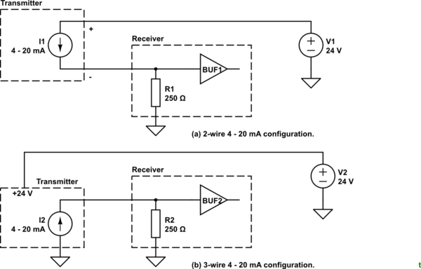
Figure 1. 2 and 3-wire 4 - 20 mA systems.

You could but it may mislead you in some circumstances. For Figure 1a your mental model would be correct. For Figure 1b it would be less so.

  1. When using a 2-wire 0 - 10 V voltage transmitter, if the input module and transmitter are fed by same power supply, will just wiring the + terminal of transmitter to the + terminal of module be enough (by wiring " - " of the module and " - " of transmitter to common)?

schematic

simulate this circuit

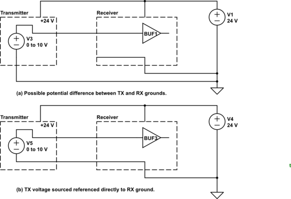
Figure 2. 0 - 10 V ground wiring.

You should reference the 0 V directly to the receiver, if possible, to eliminate voltage shift due to ground currents.

I'd like to know if the voltage produced by transmitter is always referenced to ground or can be any floating value.

It depends on the transmitter. If the transmitter has an isolated output your one-wire scheme won't work. The isolated output unit would have at least four wires: two for DC supply and two for output - signal and common.

  1. The second question is valid for also for a 4 - 20 mA 4-wire transmitter. If both input module and transmitter are fed by same power supply, will just wiring + terminal of transmitter to the + terminal of the module be enough (by wiring " - " of module and " - " of transmitter to common)?

No. The two wire transmitter will have its "-" wire connected to the input module input '+' as shown in Figure 1a. If using red and black wires then the signal return will be on the black.

On a 3-wire sensor the signal wire will not be marked '+' or '-' to avoid confusion with the supply wires.

It seems to me that a 4 wire transmitter output can be any floating value but what happens if we use same power supply for the module and the transmitter?

That would be fine.

\$\endgroup\$

Your Answer

By clicking “Post Your Answer”, you agree to our terms of service and acknowledge you have read our privacy policy.

Not the answer you're looking for? Browse other questions tagged or ask your own question.