I am new in the automation industry, and now I am focusing on learning how to wire correctly analog inputs in detail, since last time I tried I damaged the module input because of wrong wiring. Here I have several questions about analog input wiring. They may seem pointless to you but I need these answers to fully understand analog input concept. It would be appreciated if you answer these questions.
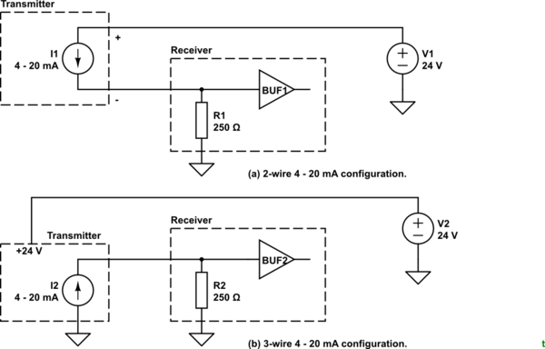
When using 2 or 3 wire 4 - 20 mA current transmitter, does analog output wire (4 - 20 mA) always produce a current referenced to the power supply common? I mean, can we think this transmitter as a fixed voltage source and a variable resistor so the minus side of the voltage source is always linked to power supply common?
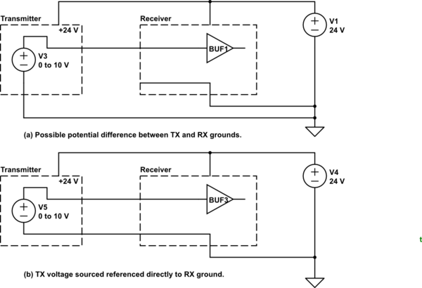
When using a 2-wire 0 - 10 V voltage transmitter, if the input module and transmitter are fed by same power supply, will just wiring the + terminal of transmitter to the + terminal of module be enough (by wiring " - " of the module and " - " of transmitter to common)? I'd like to know if the voltage produced by transmitter is always referenced to ground or can be any floating value.
The second question is valid for also for a 4 - 20 mA 4-wire transmitter. If both input module and transmitter are fed by same power supply, will just wiring + terminal of transmitter to the + terminal of the module be enough (by wiring " - " of module and " - " of transmitter to common)? It seems to me that a 4 wire transmitter output can be any floating value but what happens if we use same power supply for the module and the transmitter ?


>syntax is for quotations (parts of another document, etc.). Points 1, 2 and 3 were written by d.alex so they shouldn't be formatted as quotations. \$\endgroup\$