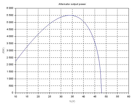
Summary: To be maximally useful an automotive alternator requires a voltage-power characteristic in the about 10V - 17V range very similar to what is shown in your graph. The rest of the (usually un-utilised) curve is a consequence of optimising an alternator to meet this requirement while minimising cost constraints.
Detail: To be "maximally useful" an automotive alternator starts charging at low engine RPM, produces maximum current "as soon as possible" and increases current as conditions allow across the engine speed range. In most cases 'nobody would complain' if an alternator
Supported sensible load (headlights, wipers, entertainment system, ...) at a reasonable idle speed and supplied perhaps a degree of battery charging as well.
Went to full or nearly full charge rating as soon as revs rose to a level which indicated normal driving use - typically 2000 rpm+. ie high enough that the alternator load did not overly compromise the available engine power.
The above behaviour would mean that
Immediately after starting car can sit at the curb in the rain, headlights and wipers on, radio or similar playing, engine idling AND battery at lead not discharging and hopefully charging slightly. And ...
As soon as travel starts the battery charge energy by starting can be replaced at the maximum rate deemed desirable by the battery charging system.
Not seen here is the RPM-Voltage curve which also has an important bearing on results. An alternator's loaded full-power output has an approximately linear voltage-RPM response. (Voltage will drop somewhat with increasing resistive-voltage-drop if load current increases with voltage (resistive load) but the voltage-RPM affect predominates). For the "idling car on a wet day" example Voltage at a sensible idle needs to be enough to provide power for the electrical load and provide a degree of charge for a typical battery, The various factors involved make this a compromise whose 'solution' is implemented by alternator performance and drive pulley settings.
This paragraph is essentially the answer to your question:
- The graph supplied is a reasonable approximation to the above need in the region of interest - which is approximately the 10-15V range at the battery and slightly higher at the alternator. Across this range (and up to about 25V) the alternator shown is approximately a 220A constant current source ! - rather more capable than most (but not all) "automotive" alternators. The rest of the alternator performance curve is a usually unutilised* consequence of implementing a design that meets the primary objective as well as possible while minimising cost.
A factor not mentioned in your formula and which will have an affect on the result is iron saturation in the magnetic field. This will set some upper current limit on alternator output at any RPM and is probably the limiting factor at all except the highest , and just possibly the lowest, voltage values shown on your graph.
As long as the P/V values shown on your graph exceed Isaturation then the alternator will (very roughly) approximate a saturation controlled constant current source. This is true only at maximum output and field control is then used to reduce output when lower power levels are required(as is usually the case).
*re "usually unutilised" - I have seen 'systems' which take advantage of this ability to produce substantially more power and voltage than is usually required.
The usual regulator is unplugged and a specialist regulator is used.
In the systems that I am aware of even higher voltages than your graph shows were available and it was possible to operate selected "mains" power tools from the system. Nowadays this could be done with a modern electronic "inverter generator" system taking input at say 50V, and boosting voltage to produce "mains AC" at 50 or 60 Hz.
An upper practical limit to this system is set by the operating breakdown voltage of the alternator diodes, and an upper theoretical limit is set by Vmax in your formula.
The system mentioned above mention existed in the 1950-1970s time frame and would have had little or no electronic content. I had the opportunity to buy such a controller "for interest" long after they had vanished from the market but, sadly, did not do so.

