4
\$\begingroup\$

I want to find the minimum resistance \$R_L\$ so as to maintain \$V_z\$(voltage of the zener corresponding to the minimum current \$I_{z_0}\$) across the same resistor \$R_L\$.
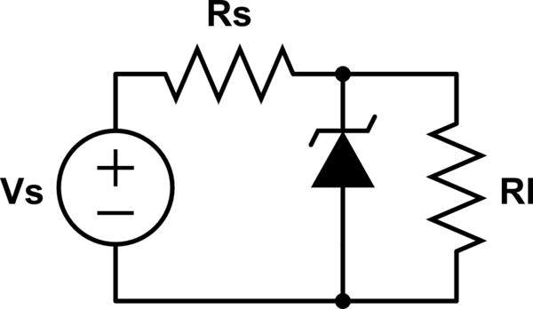
schematic

simulate this circuit – Schematic created using CircuitLab

I have two ways of looking at this, one of them is wrong and I need your help to figure it out!

First method:

I take off the diode as the load and find thevenin voltage : $$V_{th}=\frac{R_L}{R_l+R_s}V_s$$

Since

\$V_{th}=V_{R_L}\$

I'll equate it with \$V_z\$ which gives :

\$\frac{R_L}{R_L+R_S}V_S=V_z\$

thus

\$R_L=\frac{R_S.V_z}{V_S-V_z}\$

Second method:

If \$R_L\$ is minimal then \$I_L\$ passing through it would be maximal and \$I_z\$ minimal (\$= I_{z_0}\$) thus we'd have :

$$I_S = I_L+I_{z_0} \Leftrightarrow \frac{V_S-V_z}{R_S}=\frac{V_z}{R_L}+I_{z_0}\Leftrightarrow R_L=\frac{R_S.V_Z}{V_S-V_Z-R_S.I_{z_0}}$$

(I'm skeptical concerning the implication \$I_L\$ maximal \$\Rightarrow\$ \$I_z\$ minimal, or in other words \$I_z = I_{z_0}\$)

\$\endgroup\$
3
  • \$\begingroup\$ Maybe you could rearange the text in more lines, so it would be better readable. For examle 1. and 2. ,...Altrough nice use of latex equations, so +1. A good staritng point would be \$V_{R_L}=V_Z\$ \$\endgroup\$ Commented Mar 8, 2019 at 10:00
  • \$\begingroup\$ Will do! That's what I did, look at "First". \$\endgroup\$
    – GDGDJKJ
    Commented Mar 8, 2019 at 10:02
  • 1
    \$\begingroup\$ +1 from me, this is a good example of how the 'I'm confused with this circuit' questions should be asked. OP explains what they are trying to so/understand/solve, then explains their thinking behind it, and shows how they attempted to tackle the problem. \$\endgroup\$
    – MCG
    Commented Mar 8, 2019 at 10:07

2 Answers 2

1
\$\begingroup\$

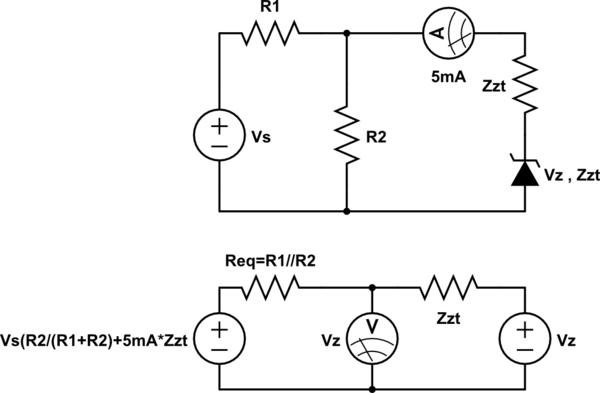
A typical 300mW Zener uses a test current Izt=5mA with an incremental resistance Zzt and a threshold current, at 1/10 Izt or It @ 0.5mA which results in a knee resistance of Zzk approx. 10x Zzt.

The same is true for LEDs.

Make a Thevenin equivalent circuit for 5mA at a low power.
This gives the low rated resistance, Zzt and is important to include in the equation to solve for R1.

schematic

simulate this circuit – Schematic created using CircuitLab

Now you can easily solve for R1

\$\endgroup\$
0
\$\begingroup\$

\$ V_S = V_{R_S} + V_Z\$

\$ V_S = I_S\cdot R_S + V_Z\$

\$ I_S = I_Z + I_L\$

\$ V_S = (I_Z + I_L)\cdot R_S + V_Z\$

\$ I_L = \dfrac{V_Z}{R_L}\$

\$ V_S = (I_Z + \dfrac{V_Z}{R_L})\cdot R_S + V_Z\$

\$ R_S =\dfrac{V_S - V_Z}{I_Z + \dfrac{V_Z}{R_L}} \$

\$ R_S =\dfrac{V_S - V_Z}{I_{Z_0}+ \dfrac{V_Z}{R_{L_{min}}}} \$

EDIT: It's not what your asking for...wait a minute...

\$R_{L_{min}}=\dfrac{R_S\cdot V_Z}{V_S-V_Z-R_S\cdot I_{Z_0}}\$

I guess you got the same.

\$\endgroup\$
2
  • \$\begingroup\$ Yes for the second method, why doesn't the first work though? For me it seems logical. \$\endgroup\$
    – GDGDJKJ
    Commented Mar 8, 2019 at 10:48
  • \$\begingroup\$ Hmm..I guess the thevenin voltage is not equal to Vz as long there is no minimal current Iz0 present. \$\endgroup\$ Commented Mar 8, 2019 at 11:02

Your Answer

By clicking “Post Your Answer”, you agree to our terms of service and acknowledge you have read our privacy policy.

Not the answer you're looking for? Browse other questions tagged or ask your own question.