1
\$\begingroup\$

I'm trying to get an SN74HC595N working with an Arduino Due. Eventually I will be hooking up each output to an NPN transistor to drive Nixie tubes (I am switching my design from a Due to using an ESP8266, so I need to cut back on the pin use, hence the shift register).

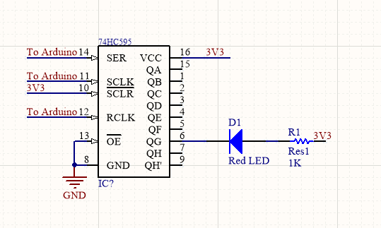
I have been using this as the schematic to get working (except using 3.3 V instead of 5 V since I'm using a Due).

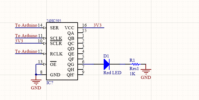
When set up according to the schematic nothing works (I'm using the same code too), however, when reversing the polarity of the LEDs and hooking them up to high, it works, so the 74HC595 is working fine as a sink, but it doesn't seem to be sourcing.

Am I missing something to make it source?

Here is what I have set up (currently only using 1 LED just to make sure things work):

enter image description here

And here is it set up with the 74HC595 as a source (which is not currently working):

enter image description here

\$\endgroup\$
9
  • \$\begingroup\$ make a single channel schematic \$\endgroup\$
    – D.A.S.
    Commented Mar 10, 2019 at 23:57
  • \$\begingroup\$ @SunnyskyguyEE75 I'm not familiar with what a single channel schematic is (unless it's just a normal schematic like you'd make in altium) \$\endgroup\$
    – soup
    Commented Mar 11, 2019 at 0:12
  • 1
    \$\begingroup\$ using the lame circuit editor herer or ASCII dwg here to show the CMOS driver supply voltages, LED, ,NPN , nixie tube and when/where your fault is.. something clearer than your explanation \$\endgroup\$
    – D.A.S.
    Commented Mar 11, 2019 at 0:15
  • 1
    \$\begingroup\$ There is nothing wrong with your schematic. There is therefore something wrong with your implementation or the parts you are using or the firmware that's controlling it. \$\endgroup\$ Commented Mar 11, 2019 at 0:47
  • 1
    \$\begingroup\$ @soup Yes, plus of course write a 1 to turn it on rather than a 0. \$\endgroup\$ Commented Mar 11, 2019 at 2:26

1 Answer 1

1
\$\begingroup\$

It looks like we’ve encountered some resistance.

enter image description here

The Pch and Nch have a wide tolerance for Vt near 1.25V and if the Vt of Pch is higher than the Nch this would explain the inability to drive the LED.

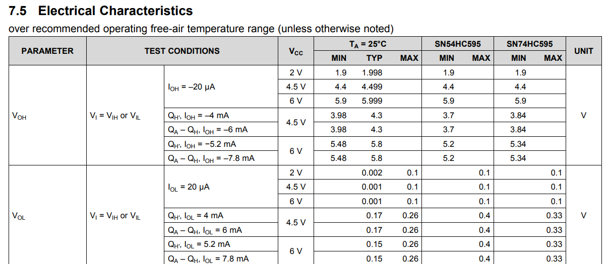
Although rated for 2~6V for the 74HC' CMOS family, the worst case specs for (Vdd-Voh) match Vol so it is the symmetrical worst case but typically, one may expect slightly weaker Pch or higher Vt thresholds. enter image description here However the guaranteed IC std. test currents are as follows;
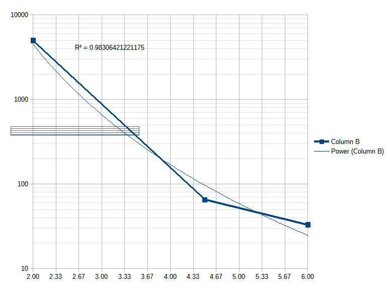
at 2V @ 25'C, Vol/Iol = 0.1V/20uA = 5k Ω = Ron " RdsOn "
at 4.5V @ 25'C, Vol/Iol = 0.26V/4mA = 65 Ω
at 6.0V @ 25'C, Vol/Iol = 0.26V/7.8mA = 33 Ω
Thus interpolating to 3.3V I expect RdsOn may 400~500 Ohms enter image description here is wishful thinking.

Conclusion:

For your prototype, you can bypass the 1K resistor.

For reliable LED driving 3.3V RdsOn performance, you can switch to the 74VHC' CMOS family 74VHC595 which is 360mV/4mA= 90 Ohms @ Vdd=3.0V

\$\endgroup\$
9
  • \$\begingroup\$ Thanks for this, I'm going to order some 74VHC595's and see if that works instead. I tried bypassing the 1K resistor, however the LED still can't be driven. \$\endgroup\$
    – soup
    Commented Mar 11, 2019 at 3:23
  • \$\begingroup\$ What voltage is across LED? 1.6? I assume you cannot invert the signal in Duo? \$\endgroup\$
    – D.A.S.
    Commented Mar 11, 2019 at 4:19
  • \$\begingroup\$ As a sink 1.7V (while using the 1K resistor). As a source with the 1K resistor, 56mV (but not changing when it should be set high).Without the 1K, 92mV again not changing even when set high. When I probe the pin voltage when it's set up as a source, it never registers at 3.3V relative to ground. \$\endgroup\$
    – soup
    Commented Mar 11, 2019 at 4:47
  • \$\begingroup\$ One other question, If I understand correctly, the issue is that the internal resistance is too high, so I don't have the necissary voltage to drive the LED, however I would expect there to still be some voltage to ground. When I replace the LED and 1K resistor with a voltmeter then, the reading should be about 3.3V since the voltmeter has a much higher resistance, however the voltmeter in this case still reads 0V (actually about 3mV when sent a 0 and 0mV when sent a 1). \$\endgroup\$
    – soup
    Commented Mar 11, 2019 at 23:47
  • 1
    \$\begingroup\$ Got the 74VHC595, everything is working well now, thanks! \$\endgroup\$
    – soup
    Commented Mar 12, 2019 at 16:18

Your Answer

By clicking “Post Your Answer”, you agree to our terms of service and acknowledge you have read our privacy policy.

Not the answer you're looking for? Browse other questions tagged or ask your own question.