0
\$\begingroup\$

An ammeter is a low resistance device connected in series with the element through which we want to measure current However, a multimeter is connected in parallel with the element under observation for current measurement. What mechanism operates there ?

It cannot measure voltage and resistance and then take the quotient as resistance can be measured when resistor is isolated.

Does it first measure the impedance of the element,say it is R and then it varies its impedance between pins to say 1000R , then impedance of this circuit is still nearly R so that we did not disturb original circuit noticeably, then it measures current through itself and multiplies it by 1000 to get the current through R.

Wikipedia https://en.m.wikipedia.org/wiki/Multimeter says (Under operation) :

For analog current ranges, matched low-resistance shunts are connected in parallel with the meter movement to divert most of the current around the coil. Again for the case of a hypothetical 1 mA, 500 Ω movement on a 1 A range, the shunt resistance would be just over 0.5 Ω.

However I don't understand it.

Please explain the solution.

\$\endgroup\$
2
  • 3
    \$\begingroup\$ You need to connect your multimeter in series when you are measuring current. \$\endgroup\$
    – The Photon
    Commented Mar 31, 2019 at 16:37
  • \$\begingroup\$ But this article talks of something parallel \$\endgroup\$
    – Kutsit
    Commented Mar 31, 2019 at 16:41

6 Answers 6

5
\$\begingroup\$

Wikipedia: ... for the case of a hypothetical 1 mA, 500 Ω movement

This means that the meter reads full scale when 1 mA is flowing through it. The voltage across the meter will be \$ V = IR = 1m \cdot 500 = 500 \ \text {mV} \$. So it will read full scale if connected across a 500 mV voltage source too.

schematic

simulate this circuit – Schematic created using CircuitLab

Figure 1. The example meter has an internal resistance of 500 Ω and will read full scale with 1 mA through it.

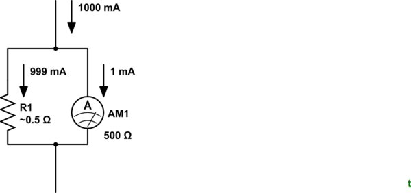
... on a 1 A range, the shunt resistance would be just over 0.5 Ω.

schematic

simulate this circuit

Figure 2. R1 "shunts" most of the current around the ammeter.

To measure 1 A without damage to the meter we need to shunt 499 mA around the meter while 1 mA runs through it. We have already calculated that the voltage drop across the meter will be 500 mV at full scale so we can calculate R1 as $$ R_1 = \frac {V}{I} = \frac {0.5}{0.999} = 0.5005 \ \Omega $$

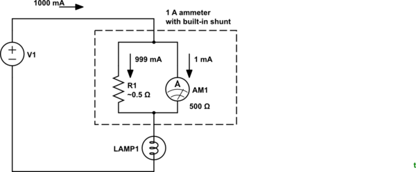
The combined meter and shunt is always wired in series with the circuit being measured.

schematic

simulate this circuit

Figure 3. Correct measurement technique.

From the comments:

You need to connect your multimeter in series when you are measuring current. – The Photon

But this article talks of something parallel – Shlok Vaibhav

It is describing the meter being in parallel to the shunt which is in series with the circuit being measured. Hopefully this is clear now.

\$\endgroup\$
5
\$\begingroup\$

This is the paragraph in question:

For analog current ranges, matched low-resistance shunts are connected in parallel with the meter movement to divert most of the current around the coil. Again for the case of a hypothetical 1 mA, 500 Ω movement on a 1 A range, the shunt resistance would be just over 0.5 Ω.

They are describing the internal workings of the meter. You always connect the meter itself in series with the current you want to measure so all the current goes through the meter.

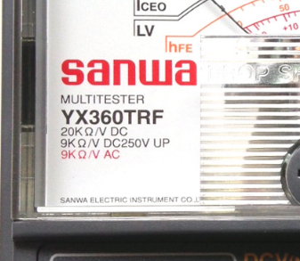
Inside the meter there will be a shunt resistor and a voltmeter, at least in the case of digital meters. Analog meters are inherently current meters, but they are made to deflect fully with a very small current, so the shunt divides the current allowing a fixed portion to go through the meter movement (except perhaps on the lowest DC current range). A typical analog multimeter, more realistically, would have a movement that would deflect fully with some tens of uA. The Sanwa meter shown has a sensitivity of 20,000\$\Omega\$/V so it is a 50uA (full scale) movement. You can also see that the lowest DC current range is 50uA full scale.

enter image description here


At some point you might wonder how a shunt divides current in the case where the underlying meter is a D'Arsonval moving coil movement- ideally, putting a shunt resistor in parallel would have no effect (look at the current divider equation), but real meter movements have significant internal resistance, so you would shunt the movement with a fraction of that resistance, and likely you would add some resistance on top of the copper resistance. And if that series resistance you added happened to have a slight negative temperature coefficient it might compensate for the positive temperature coefficient of the copper coil.

\$\endgroup\$
4
\$\begingroup\$

For current measurement the multimeter should be connected in series with the circuit under test. There is usually a separate input for one of the wires which hooks into the multimeter's internal shunt resistor. The multimeter is therefore measuring the voltage drop across its own internal shunt resistor, and from the voltage and known resistance it can calculate the current.

\$\endgroup\$
2
  • \$\begingroup\$ Thanks but this article talks of something parallel \$\endgroup\$
    – Kutsit
    Commented Mar 31, 2019 at 16:41
  • 1
    \$\begingroup\$ I'm not sure what article you refer to. If you mean Wikipedia, you need to edit your answer to show where that text came from so we can figure out the context. \$\endgroup\$
    – Sean
    Commented Mar 31, 2019 at 16:42
3
\$\begingroup\$

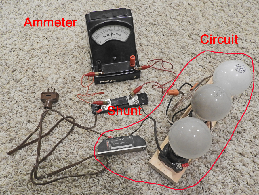
The quoted Wikipedia article describes a shunt in parallel with a meter movement. An analog meter movement is an ammeter. The shunt and the resistance of a meter movement form a current divider. For the overall picture, the meter movement may be packaged as an ammeter with the shunt external to the meter. For measurement of current in a circuit, the shunt and meter movement together form an ammeter that must be connected in series with the circuit or part of a circuit where the current needs to be measured.

The image below shows an ammeter (-500 - 0 - + 500 microamps) and a shunt connected to a circuit.

enter image description here

\$\endgroup\$
2
\$\begingroup\$

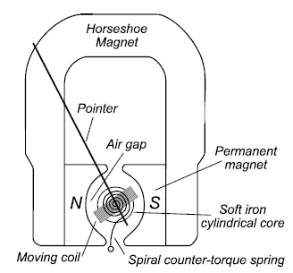
The Analog Multimeter uses a D'Arsonval analog moving coil meter movement.

enter image description here

The meter movement works on the motor principal, where current is applied to a coil wrapped around an iron core between a permanent magnet. The current magnetizes the iron core and the coil rotates proportional to current applied. This current is limited by the current which causes full-scale deflection, say \$I_{FSD} = 50 \mu A\$.

A current greater than \$I_{FSD}\$ would cause the analog needle to be pinned to the mechanical stop as the needle attempts to turn to the level.

So the analog multimeter in question can measure VDC, ADC, VAC, Ω, C, ±VDC. Each setting uses different circuits to convert the scale selected to achieve the appropriate 0 to 50μA.

As a Voltmeter, the meter is connected in parallel with the load being measured, but internally the meter movement is connected in series with a resistor dropping the majority of the voltage only allowing a small proportion across the meter movement.

As an ammeter, the meter is connected in series with the circuit, but internally the meter movement is connected in parallel with a shunt resistor. If the meter is set on 2.5mA and 2.5mA is applied, 2.45mA would go through the shunt and 50μA would go through the meter movement.

So an analog ammeter is connected in series, but internally the analog meter movement has to be connected in parallel because of the current which causes full-scale deflection \$I_{FSD}\$.

\$\endgroup\$
0
\$\begingroup\$

Rules are changed, you can measure current without series connection, you can able to measure current parallelly like voltage across a diode. You can surf you tube as current measurement without series connection. You can able to see a proof.

\$\endgroup\$
2
  • 1
    \$\begingroup\$ You can't make a current measurement without some kind of a series connection. You can make a voltage measurement of a known resistance and then use I = V*R to find the current, but then it's a voltage measurement, not a current measurement. \$\endgroup\$
    – Voltage Spike
    Commented Apr 18, 2020 at 3:56
  • \$\begingroup\$ Welcome to EE.SE. I've seen that video, in fact it puts the meter in series with the branch of the circuit. It's a nifty trick but has a big flaw. As soon, as you remove the meter tips the forward voltage of the diode is inserted and the behaviour of the circuit is modified. So what you measure is probably not, what happens in the circuit, when you don't measure. \$\endgroup\$
    – Ariser
    Commented Apr 18, 2020 at 22:15

Your Answer

By clicking “Post Your Answer”, you agree to our terms of service and acknowledge you have read our privacy policy.

Not the answer you're looking for? Browse other questions tagged or ask your own question.