0
\$\begingroup\$

I have this schematic:

schematic

I had to replace T1 transistor with a MOSFET (because D4 on an ESP8266 has to be high at boot time and the transistor reduces the pin voltage, so the ESP doesn't boot - see my previous question).

So I replaced it with a IRF3205 MOSFET datasheet (I know it is total overkill) base = gate; source = emitter; drain = collector.

The LED works (i.e. it turns off and on) but the LED in the "ON" state is really dim. What is wrong? It has to be something elementary, but I can't figure it out.

The LED is inside a button (12 V with internal resistor). D4 is the ESP8266 pin (3.3 V logic)

Thanks.

\$\endgroup\$
2
  • 4
    \$\begingroup\$ This FET is not designed to be driven with 3.3V. \$\endgroup\$
    – Hearth
    Commented Apr 10, 2019 at 19:12
  • 2
    \$\begingroup\$ Look at the Vgs in the "Conditions" column in the row for RDSon of the specs table. \$\endgroup\$
    – DKNguyen
    Commented Apr 10, 2019 at 19:14

2 Answers 2

5
\$\begingroup\$

This FET is not designed to be driven by 3.3V logic.

enter image description here

The threshold voltage is the gate-to-source voltage at which the FET is just barely on. This is not the point at which the FET is fully on, which would require quite a bit more than the threshold voltage.

\$\endgroup\$
7
  • \$\begingroup\$ Ok, thanks. So I will have to order some mosfet with lower Vgs.. If I understand by datasheet Vgs voltage could be somewhere between 2-4V so if I drive it with 3.3 the threshold is not meet and mosfet is not fully open so it limits current D-S. It is right ? \$\endgroup\$
    – Fires_CZ
    Commented Apr 10, 2019 at 19:18
  • 2
    \$\begingroup\$ Even if you do reach the threshold voltage, the current is proportional to \$V_{GS} - V_{GS,th}\$. You need to be substantially above the threshold voltage. Look for "logic-level" FETs. \$\endgroup\$
    – Hearth
    Commented Apr 10, 2019 at 19:22
  • \$\begingroup\$ Yet this is the problem but not the solution \$\endgroup\$
    – D.A.S.
    Commented Apr 11, 2019 at 13:24
  • \$\begingroup\$ @SunnyskyguyEE75 Yes. This is answering the question "What is wrong?" that the asker asked. \$\endgroup\$
    – Hearth
    Commented Apr 11, 2019 at 14:02
  • \$\begingroup\$ As EE's we must think outside the Question only and give an answer that ALSO solves the problem rather than simply answer the incomplete question , what is wrong. But this is a systemic issue on this site. We constrain ourselves to just the question, when we need to think outside the little box. \$\endgroup\$
    – D.A.S.
    Commented Apr 11, 2019 at 14:05
-1
\$\begingroup\$

When you see a Vgs(th) for a FET. You will need at least 2 to 3x Vgs(th) (threshold) conduct fully.

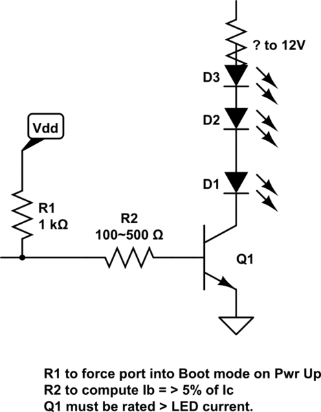
Change **to R = 500 Ohms or less depending on LED string current such that input current is 5~10% of switched output current.**

IRFxxx FETs are Vgs(th)=3V +/-1 tolerance This is the threshold for 500uA not Amps !!

So you need >4.5V for Vgs or this IRFxxx family of FETs and preferably 10V for rated RdsOn as shown in specs.

You ONLY get 10% of hFE = Beta as a saturated switch.

We want to ensure base current = >5% of LED current. Preferably 10%. (never use Vgs(th)2~4V FETS on 3.3V logic. It needs >5V.) All IRFxxx's I think are this way, Now they make Logic level FETS with a different prefix in P/N.

Your design was (3.3V-0.6Vbe)/5k=Ib= 540 uA.

Change Rb to >= 100 Ohms and it will work off any 3.3V logic and NPN open collector. Iout=(3.3-Vbe)/(Rcmos+Rs)= (3.3-0.7)/(33+100)=20 mA so it can drive 200mA to 350mA on collector with low Vce(sat)

Adjust series Rs as required.

schematic

simulate this circuit – Schematic created using CircuitLab

\$\endgroup\$
7
  • \$\begingroup\$ Rb is 5kilo ohms. Not 50ohms. \$\endgroup\$
    – Fires_CZ
    Commented Apr 11, 2019 at 5:05
  • \$\begingroup\$ Yes it was and that's why it was dim Try 500 Ohms then 100 Ohms if needed \$\endgroup\$
    – D.A.S.
    Commented Apr 11, 2019 at 5:06
  • \$\begingroup\$ If it gets hot then you need a power transistor \$\endgroup\$
    – D.A.S.
    Commented Apr 11, 2019 at 5:11
  • 1
    \$\begingroup\$ With transistor brightness was ok. .. But board don't boot because it drops the voltage on D4 (D4 is special pin what has to be in login high in the boot time) \$\endgroup\$
    – Fires_CZ
    Commented Apr 11, 2019 at 5:22
  • \$\begingroup\$ I thought I told you in a previous question to use a 1k Pullup resistor \$\endgroup\$
    – D.A.S.
    Commented Apr 11, 2019 at 13:17

Your Answer

By clicking “Post Your Answer”, you agree to our terms of service and acknowledge you have read our privacy policy.

Not the answer you're looking for? Browse other questions tagged or ask your own question.