18
\$\begingroup\$

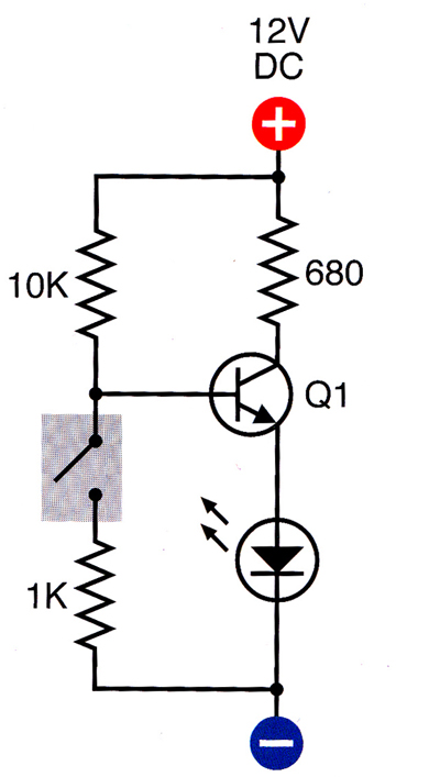
I am studying electronics and I am currently reading/working my way through "Make: Electronics" by Charles Platt. Here is one of the circuit diagrams that he gives for making a basic burglar alarm: alarm circuit

My question is, what is the purpose of the 1K resistor after the switch. I understand the point of all the other components, but why does that resistor have to be there? I have re-read this part of the book a few times but it doesn't seem to mention why that resistor is there or what it does. Can it be omitted?

\$\endgroup\$
2
  • 2
    \$\begingroup\$ When the switch is closed, the 10K and 1K resistor form a voltage divider. \$\endgroup\$ Commented Oct 11, 2012 at 0:49
  • 3
    \$\begingroup\$ It's probably just to attenuate current transients when discharging the input capacitance of the transistor when closing the switch. It will consequently also slow down the turn-off time a bit. \$\endgroup\$ Commented Oct 11, 2012 at 0:52

5 Answers 5

16
\$\begingroup\$

The 10K and 1K resistors in the circuit form a voltage divider when the switch is pressed closed. With the +12V supply this divider nominally sets a transistor base bias voltage at about 1 volt. Very little base current flows due to the fact that the emitter of the NPN transistor is held above ground and as such the NPN base emitter voltage never gets high enough to let the transistor turn on. In a simulation of such circuit with a 2N3904 transistor model it shows that the presence of the 1K resistor keeps some bias across the LED of about 0.7V due to very low level currents in the transistor . If the 1K resistor is removed and when the switch is closed to GND then the bias across the LED drops to essentially zero because the transistor becomes fully turned off.

From a functional standpoint to get an LED to turn on and off from the switch there is no need to have the 1K resistor as relates to just this simple circuit. On the other hand if this circuit was used in a more complex system that had a monitor circuit across the LED looking for the above mentioned bias it could be an indicator that all the wiring from the switch to the LED was intact and in place. In an real burglar alarm system where the switch and LED may be located far apart this residual bias detection can play a role to ensure that the wiring has not been tampered with.

\$\endgroup\$
0
11
\$\begingroup\$

You are right, the 1 kΩ resistor is pointless. When the switch is closed, is causes the base of the transistor to go low enough to turn it off, but outright shorting the base to ground would unambiguously achieve the same effect.

I don't really like this circuit much. In this case, I don't see the point to putting the LED in the emitter leg. It seems a convoluted way of doing things with no real benefit.

Given all the above, I wouldn't look to anything in that book as examples of good design.

\$\endgroup\$
9
\$\begingroup\$

If the switch is open the base voltage is determined by the LED's forward voltage, for instance 2 V + 0.7 V = 3.7 V. Then the base current is (12 V - 3.7 V)/ 10 kΩ = 0.83 mA.

If you close the switch the current through the 10 kΩ resistor will be split to go partly through the 1 kΩ resistor, and partly into the base. We know the base needs 3.7 V before the transistor will begin conducting. To have 3.7 V there the current through the 1 kΩ will have to be 3.7 mA, due to Ohm's Law. So if the transistor would conduct, its base current will be 3.7 mA less than the current from the 12 V supply through the 10 kΩ resistor.

But we saw that that current won't be higher than 0.83 mA, so everything will go through the 1 kΩ and the transistor won't conduct at all. Since it doesn't conduct we can ignore it for now, and calculate the base voltage from the resistor divider:

\$ V_B = \dfrac{1 k\Omega}{1 k\Omega + 10 k\Omega} \times 12 V = 1.09 V\$,

which indeed is lower than the required 3.7 V.

What if the 1 kΩ was omitted? Then the ground current would increase from 1.09 mA to 1.2 mA, that's all. That 0.1 mA difference won't break the bank, so you might as well omit it.

Frankly, I don't think this is a good circuit. You close the switch to switch the LED off, instead of on, which is, well, OK, but it means that when the LED is off you'll still have a current of 1.1 mA flowing, for nothing. It would be a better idea to place the switch on the 10 kΩ side. Admitted, it's function would be inversed (closing would switch the LED on), but you won't have a current with the LED off. In that case you still can add a resistor to ground, but its value should be much higher: a 4.5 kΩ will draw 0.83 mA at 3.7 V base voltage. That 0.83 mA was the current coming from the 12 V supply, so that's the point at which the transistor only just begins to conduct. So the value must be higher than that. A 100 kΩ value will draw 37 µA when the transistor conducts, so the base will get 830 µA - 83 µA = 750 µA. If you don't care about the 10 % loss you can place the resistor. You can also omit it there (not replacing it with a wire!), then the base will float when the switch is open. For a bipolar transistor that's not really a problem, especially since you would need a high 3.7 V to get it conducting, but for a MOSFET that resistor would be required.
\$\endgroup\$
0
\$\begingroup\$

Current will find the path with lowest R. Switch Off, the divider will clamp the Base voltage to 1V which is not sufficient to turn on the Transistor. Switch On, the current will flow into the transistor and turn on the Vbe and Diode.

\$\endgroup\$
2
  • \$\begingroup\$ About the 680ohm on Collector, I think it is to limit the input current, namely Ice. \$\endgroup\$
    – Wim
    Commented Aug 26, 2017 at 8:54
  • \$\begingroup\$ Welcome to EE.SE, @Wim. "Current will find the path with lowest R." This should probably be, "Current will divide into parallel paths in proportion to the inverse of each path's resistance." It's not as catchy, but your version suggests that all the current will flow in the path with lowest R. \$\endgroup\$
    – Transistor
    Commented Aug 26, 2017 at 9:10
0
\$\begingroup\$

I read from your question, that the circuit is an example of burglar alarm.

Therefore I think that the function of that resistor is to avoid that some intruder burns your "very sophisticated" alarm, by putting a 9V battery directly between the switch contacts.

Another function of that resistor (maybe in the book are later explained to improve such burglar) is that maybe it's embedded on the switch. In this way, if an intruder just shorts the wires (i.e he/she makes a direct short between base and ground), the resistance will actually be 0. Therefore you can add a comparator that monitors the base voltage. If it gets too low, then the alarm should turn on anyway, as an intruder attempted to tamper your alarm.

A part from this, the resistor has no other pratical functions: it could have been omitted.

Why this strange arrangement (NPN transistor, LED on the emiter SIDE). Well, if you consider the switch and the resistor as a single component, you'll notice that they both have the ground connected to one terminal. Maybe this might be useful in some circumstances?

\$\endgroup\$

Your Answer

By clicking “Post Your Answer”, you agree to our terms of service and acknowledge you have read our privacy policy.

Not the answer you're looking for? Browse other questions tagged or ask your own question.