4
\$\begingroup\$

I'm currently studying the textbook Fundamentals of Electric Circuits, 7th edition, by Charles Alexander and Matthew Sadiku. Chapter 1.7 Problem Solving gives the following example:

Example 1.10

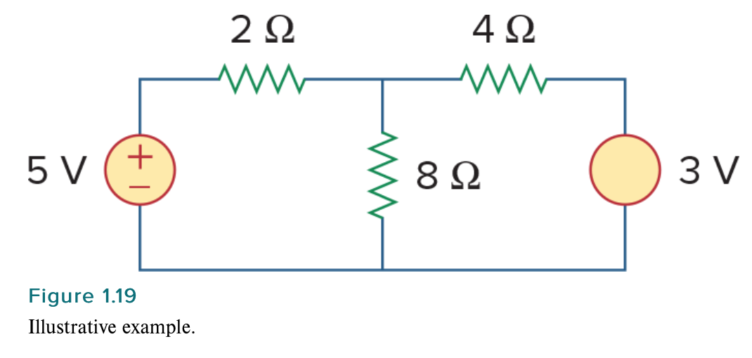
Solve for the current flowing through the \$8 \ \Omega\$ resistor in Fig. 1.19. enter image description here

Solution:

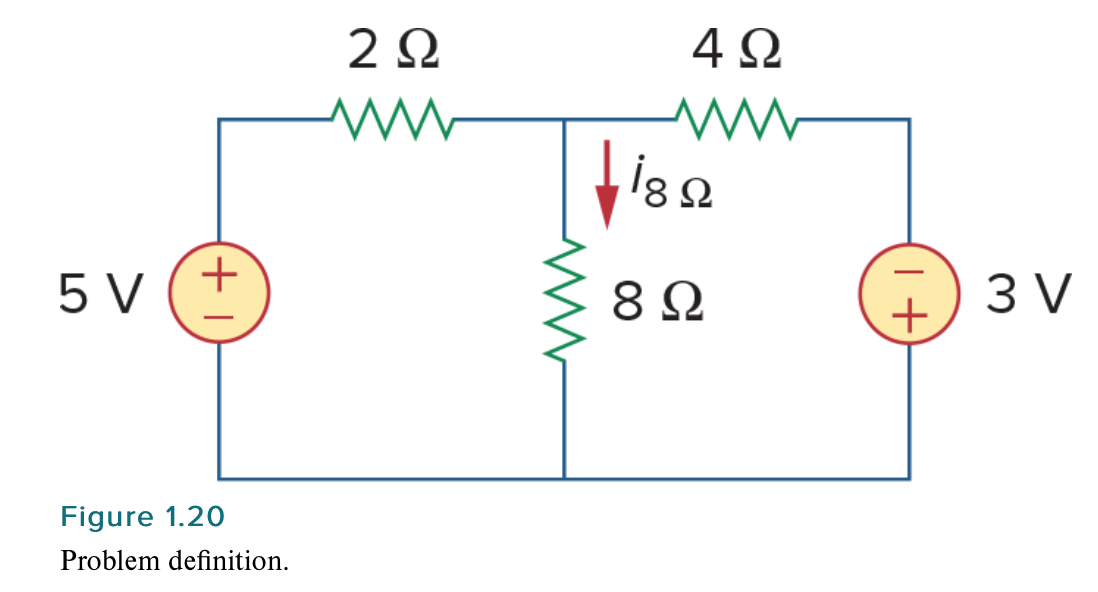
  1. Carefully define the problem. This is only a simple example, but we can already see that we do not know the polarity on the 3-V source. We have the following options. We can ask the professor what the polarity should be. If we cannot ask, then we need to make a decision on what to do next. If we have time to work the problem both ways, we can solve for the current when the 3-V source is plus on top and then plus on the bottom. If we do not have the time to work it both ways, assume a polarity and then carefully document your decision. Let us assume that the professor tells us that the source is plus on the bottom as shown in Fig. 1.20. enter image description here

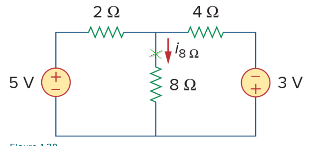
Notice that the authors have claimed (without justification) that the current is flowing downwards through the \$8 \ \Omega\$ resistor. In SpiRail's answer here, they have also shown that, for the case where the polarity is + on the bottom, the current flows downwards through the \$8 \ \Omega\$ resistor (see the red arrow): enter image description here How does one know that the current is flowing downwards through the \$8 \ \Omega\$ resistor? This seems to be the immediate assumption, but there's no explanation from the authors as to why this is the case.

\$\endgroup\$
5
  • 5
    \$\begingroup\$ If the current calculation shows it is negative, then the assumption was wrong, which is not really a problem. \$\endgroup\$ Commented Nov 25, 2021 at 17:05
  • 2
    \$\begingroup\$ At the end of the analysis if that current is found negative it will mean the real direction is reverse. if found positive the assumed direction is same. At the beginning not proven. \$\endgroup\$
    – cm64
    Commented Nov 25, 2021 at 17:08
  • 7
    \$\begingroup\$ Ahh, ok, I see. So it's effectively just a placeholder assumption. \$\endgroup\$ Commented Nov 25, 2021 at 17:09
  • 3
    \$\begingroup\$ Yes exactly it is \$\endgroup\$
    – cm64
    Commented Nov 25, 2021 at 17:10
  • 1
    \$\begingroup\$ Always define assumptions for conventional directions. It's all relative to these, just like gnd=0V anywhere you choose. \$\endgroup\$
    – D.A.S.
    Commented Nov 25, 2021 at 17:11

4 Answers 4

9
\$\begingroup\$

No, the authors have not declared that the current \$i_8\$ is flowing downward. They have defined some current named \$i_8\$ that is flowing downward. Once the circuit is solved it may be found that the value of \$i_8\$ is negative. In that case, we know that there is actually a positive current flowing up.

We must label some assumed direction for all currents and some assumed polarity for voltages so we can write meaningful and consistent equations for the circuit. If the resulting values come out negative it just means that our assumptions were not correct, but it is a perfectly valid way to start a problem.

\$\endgroup\$
4
\$\begingroup\$

How does one know that the current is flowing downwards through the resistor?

In general for this type of problem you don't know which way the current is flowing. You make an assumption about the direction, which might be an arbitrary choice, and you document your assumption, here done with the red arrow. Then you solve for the value of the current assuming it flows in your chosen direction, using techniques you are presumably now learning.

If the value turns out to be negative then the current is flowing in the opposite direction to your assumption. And if it's positive your guess was correct.

\$\endgroup\$
1
  • 1
    \$\begingroup\$ Would my downvoter care to explain the problem, so I can improve for the future? \$\endgroup\$
    – Graham Nye
    Commented Nov 25, 2021 at 20:37
4
\$\begingroup\$

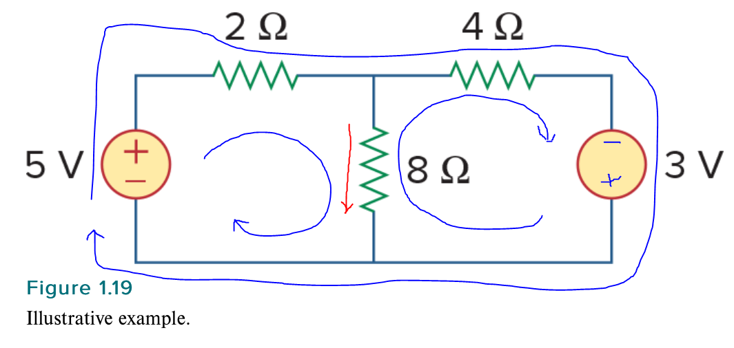
There is nothing wrong with the methodical approach suggested in the other answers (in fact, it's usually preferable), but we can double-check the results by imagining the 8\$\Omega\$ resistor is removed and what the polarity of the voltage from the erstwhile top terminal would be relative to the lower terminal of the 8\$\Omega\$ resistor (consider that 'ground').

enter image description here

If the remaining resistors were equal in value, the voltage would be positive since |5V| > |3V|. If the two voltages were equal and the resistor in series with the positive supply had less resistance than the other, then the voltage would also be positive. Both are true here, so the voltage is definitely positive.

Numerically we know it's \$K \cdot\$ (5V/2\$\Omega\$ - 3V/4\$\Omega\$)

where K = 1/(1/2+1/4) - you don't have to be able to do that in your head to see the sign of the result.

Therefore the current will flow in the indicated direction.

Now if you swapped the two resistors, it would not be as obvious, but after a bit of thought, the current would flow in the opposite direction since 5/4 < 3/2.

\$\endgroup\$
1
  • 2
    \$\begingroup\$ A very good intuitive explanation... Congratulations on having the courage to do so. \$\endgroup\$ Commented Nov 27, 2021 at 14:09
1
\$\begingroup\$

I will further develop Spehro Pefhany's intuitive explanations with some interesting observations on this configuration that is widely used in electronic circuits (with resistors having higher resistance).

This approach has the advantage over the mechanical use of formal methods of analysis because it aids understanding and makes a connection between simple electrical circuits and their more sophisticated applications in electronics.

As Spehro said, the task is to find the voltage of the upper node relative to the lower node (ground). This will automatically show the current direction through the 8 ohm resistor. So, we can remove it and consider only the 2-resistor network.

"Pull-up" and "pull-down" resistors in series

Thus we get the famous circuit arrangement used in op-amp inverting amplifiers that consists of two voltage sources with opposite polarity connected through resistors to a common point. Each of them struggles to change the node voltage in its direction. Figuratively speaking, like in the game of "tug of war", the left (+5V) source "pulls" the common point up while the right (-3V) source "pulls" it down.

If the sources have the same voltage and the resistors have the same resistance, the voltage at the common point will be zero (the so-called "virtual ground"). Let's label the left voltage source with V1 and the right one with V2, the left resistor with R1 and the right one with R2. Then V1 will appear across R1 and V2 will appear across R2… and the same current I = V1/R1 = V2/R2 will flow through this circuit of four elements (V1, R1, R2 and V2) in a loop.

Current source and current sink in series

Thus the combination of the left two elements (V1 and R1) in series acts as a current source that sources a current I1 = V1/R1 and the combination of the right two elements (V2 and R2) in series acts as a current sink that sinks a current I2 = V2/R2… and I1 = I2.

Now, if we increase V1 so V1 > V2 or we decrease R1 so R1 < R2 (the OP's case), the left source will try to source higher current than the right source can sink. As a result, because it is impossible for a current in a circuit of series-connected elements to be different, the voltage of the common point will become positive… and, if we reconnect the 8 ohm resistor, a current will flow downwards through it...

2-input voltage divider

From another viewpoint, the two resistors in series form a more sophisticated voltage divider with two inputs. It can be controlled both from the left thus producing a partial voltage V+ = V1.R2/(R1 + R2) and from the right thus producing a partial voltage V- = V2.R1/(R1 + R2). Since the denominators of the two fractions are the same, we can compare only the products. So, we see that V1.R2 > V2.R1, i.e., the node voltage is positive.

Voltage summer with weighted inputs

This is a good illustration of the superposition principle that shows this circuit sums two voltages with weighted coefficients K1 = R2/(R1 + R2) and K2 = R1/(R1 + R2) . So it acts as a voltage summer with weighted inputs. We see that K1 > K2 and draw a conclusion that the node voltage is positive.

Bridge circuit

A more sophisticated intuitive approach is to think of this circuit as of a kind of bridge. In the simplest case, if V1 = V2 and R1 = R2, the "bridge" is balanced and the node voltage is zero. When the values ​​of voltages and resistances change, the bridge becomes unbalanced and a node voltage appears.
\$\endgroup\$

Your Answer

By clicking “Post Your Answer”, you agree to our terms of service and acknowledge you have read our privacy policy.

Not the answer you're looking for? Browse other questions tagged or ask your own question.