0
\$\begingroup\$

A 1.4 A shunt DC motor, with brushes, in a home made pottery wheel from 1970s runs slightly erratically.

In general I am well impressed with it as the motor choice is appropriate for the application, being low speed and even running under varying load. The speed controller circuit board is also home made but I think the fault may be simple to correct (not sure as I am amateur.)

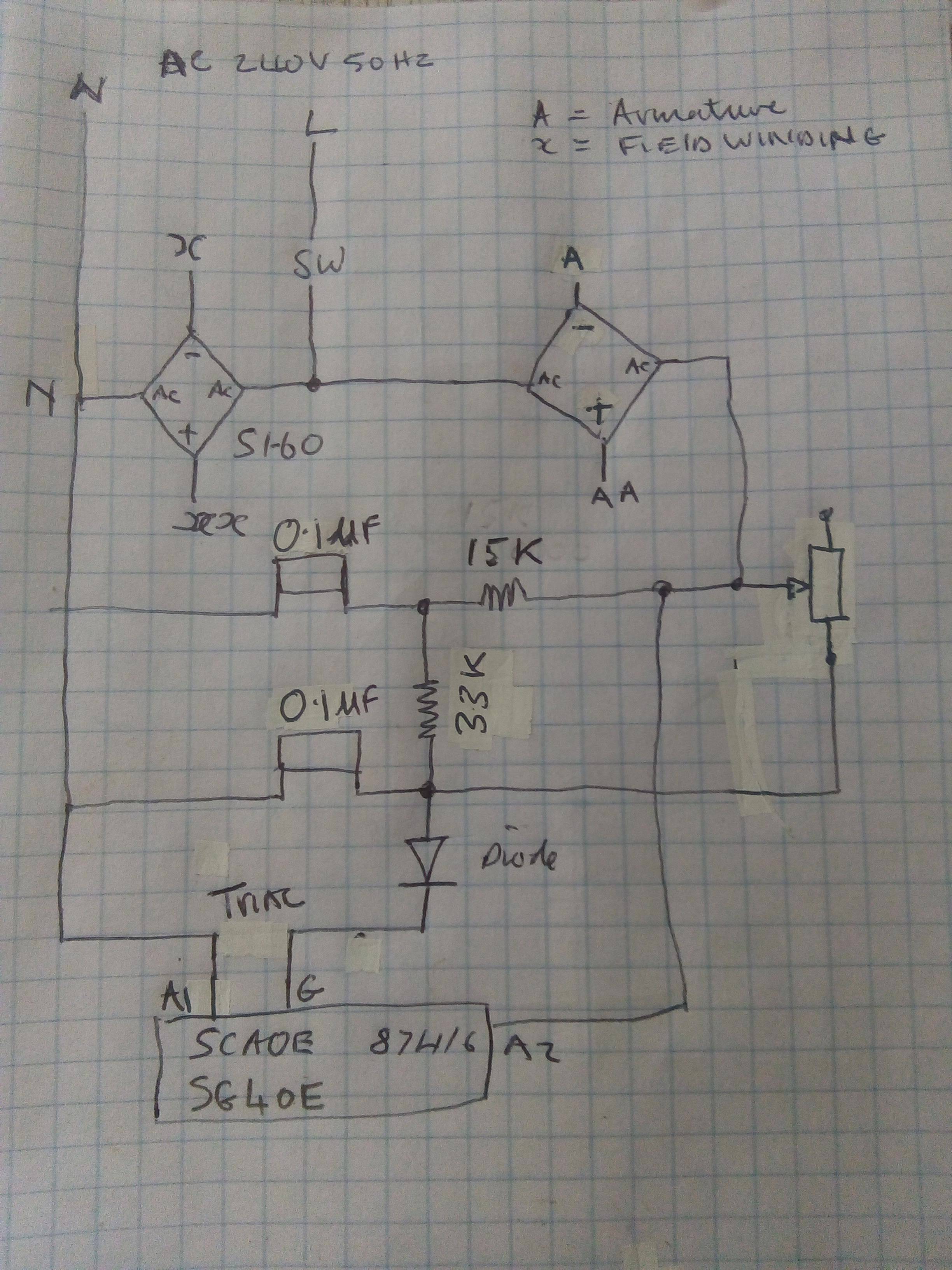
In the attached circuit diagram there are two bridge rectifiers with connections "x and xx" to field windings and "A and AA" to armature.

The field winding rectifier is about 10mm diameter "S1-60" and the armature rectifier is grey square with 400 V printed on it. So this looks as if the circuit controls armature current, but would it be better if the winding current was controlled? If so can I swap the motor wires between rectifiers? Would the rectifiers still be appropriate?

Notes

33 kΩ resistor may be 22 kΩ, 0.1 μF components look like Mullard capacitors - I have not used symbol and value may be wrong.

Speed controller circuit diagram

\$\endgroup\$
2
  • \$\begingroup\$ Field winding uses a fraction of the armature power, and the rectifiers are rated accordingly. Don't swap them! (Also, reducing field current will make the motor run faster with much less torque available ... the very opposite of what you want in a pottery wheel. \$\endgroup\$
    – user16324
    Commented May 5, 2019 at 17:09
  • \$\begingroup\$ DC motors can draw up to 10x rated current if you accelerate at full voltage, so limiting the rate of speed control depends on bridge and Triac ratings and time it takes to reach full speed. This is normal. \$\endgroup\$
    – D.A.S.
    Commented May 5, 2019 at 17:17

1 Answer 1

0
\$\begingroup\$

So this looks as if the circuit controls armature current?

It controls armature voltage.

would it be better if the winding current was controlled?

Controlling armature current with an outer voltage or speed control loop would be better, but more complex.

By "winding current" I suspect you mean field winding current as apposed to armature winding current. Controlling the field winding current would make the minimum operating speed about equivalent to the present maximum speed. Reducing the field current will increase the speed and reduce the torque capability. I doubt very much that is what you want.

The above seem to be the only actual questions asked. The question seems to imply that you wish to improve the control scheme because the motor " runs slightly erratically." You have not actually described what aspect of motor performance is undesirable.

Speed decrease with increased load is normal for a simple armature voltage control.

Random speed variation with a steady load could be due to line voltage variation, other power quality issues, motor brush problems or a loose connection. Failure to start relably would like be a brush problem.

\$\endgroup\$
3
  • \$\begingroup\$ The erratic running I mentioned is a bit like hunting or something getting out of sync and correcting itself, happens about every two seconds. \$\endgroup\$
    – user36093
    Commented May 5, 2019 at 17:45
  • \$\begingroup\$ Perhaps it is an interaction between the motor and the AC power source. Check to see if the input voltage fluctuates corresponding to the speed fluctuations. \$\endgroup\$
    – user80875
    Commented May 5, 2019 at 18:08
  • \$\begingroup\$ Actually, it seems the motor runs more smoothly at faster revs so I will solve it by adding a pull speed reduction. \$\endgroup\$
    – user36093
    Commented May 5, 2019 at 18:55

Your Answer

By clicking “Post Your Answer”, you agree to our terms of service and acknowledge you have read our privacy policy.

Not the answer you're looking for? Browse other questions tagged or ask your own question.