0
\$\begingroup\$

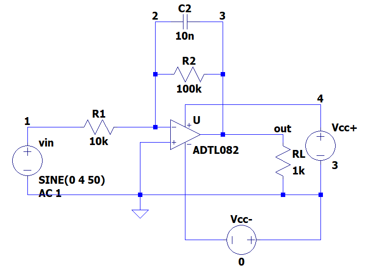
I'm simulating the low-pass inverting amplifier circuit using LTSpice:

enter image description here

I put a sine of amplitude 4 as input to see the behaviour of the op-amp in the non-linear zone. I was taught that the output voltage, in non-linear zone, can't exceed the positive supply voltage and can't be smaller than the negative supply voltage:
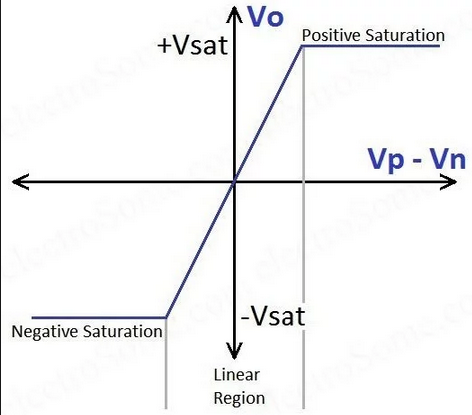
enter image description here

However, when running the simulation I get that the output, i.e. the voltage on the load resistance (V(3) on the simulation), gets smaller than the negative supply voltage (0):
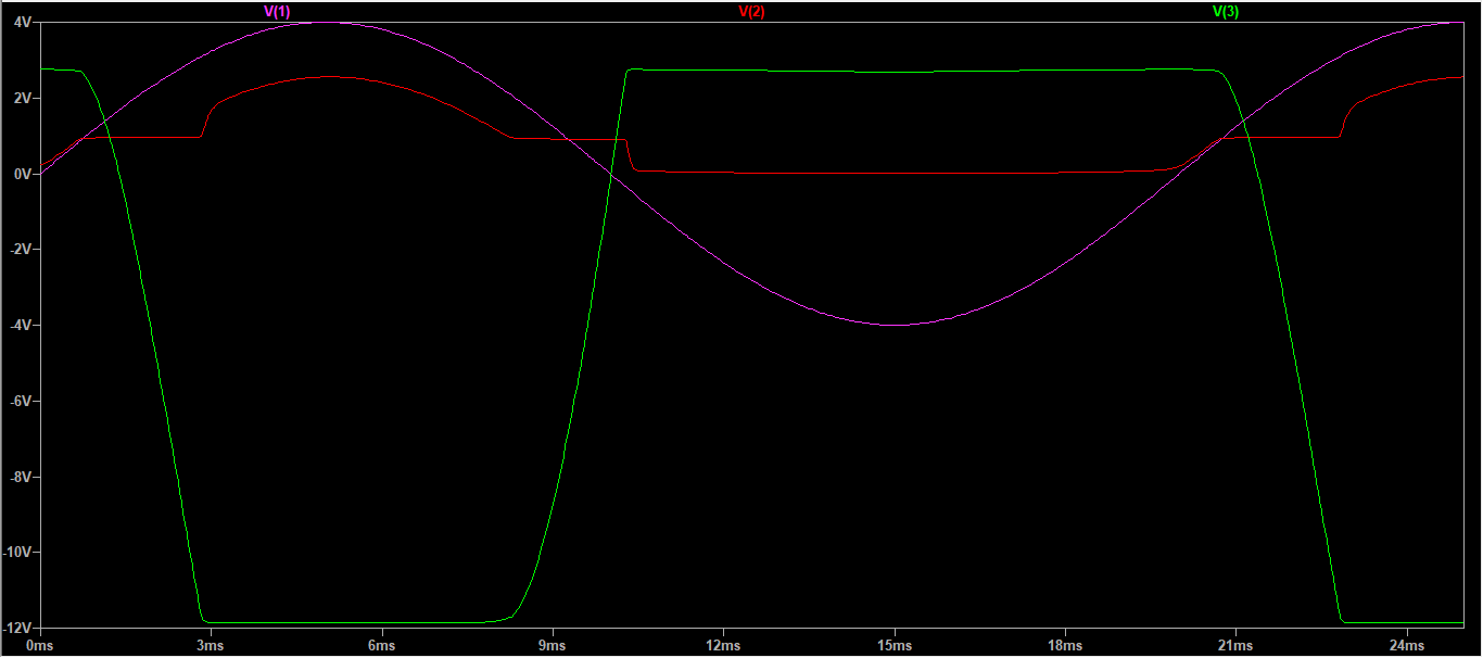
enter image description here

How can this happen?

\$\endgroup\$
3
  • \$\begingroup\$ Try the LTspice universal op amp \$\endgroup\$
    – sstobbe
    Commented May 25, 2019 at 14:07
  • \$\begingroup\$ That worked, thank you! The teacher had used this other model when simulating some other circuit and I mistakenly used it, \$\endgroup\$
    – Lucen
    Commented May 25, 2019 at 14:14
  • \$\begingroup\$ Glad to hear it. Your understanding of op-amps is correct you just got a bad spice model with regards to power supply inputs \$\endgroup\$
    – sstobbe
    Commented May 25, 2019 at 14:50

1 Answer 1

0
\$\begingroup\$

For low input current reasons the Op Amp you selected is designed for +/-5V minimum due to the 4V FET biasing and the common mode rejection ratio or CMRR input range is 4V above the negative supply rail. (which you show as 0V)

Meanwhile, you are supplying +3V, 0V supply and driving it with 4Vp sine, so you can expect errors when you violate the specs. How the faults are simulated may not be handled well, but you must be aware of the requirements for supply voltage and CM input range.

\$\endgroup\$

Your Answer

By clicking “Post Your Answer”, you agree to our terms of service and acknowledge you have read our privacy policy.

Not the answer you're looking for? Browse other questions tagged or ask your own question.