1
\$\begingroup\$

I need to switch a 12 VDC circuit (automotive ignition coil) with a .6vdc signal from an impulse coil. I am trying to replace the ignitor box for this engine; they are extraordinarily expensive and cannot be tested. From what I have read, this may require a germanium transistor to increase voltage sufficiently to perhaps use a MOSFET for the twelve volt circuit. This ignition system fires the ignition coil by interrupting the path to ground for the primary circuit of the ignition coil as opposed to the circuits with which I am familiar, i.e., interrupting the power side of the primary coil. I know just enough about electronic circuits to get into trouble.

Not a model t; oddly enough, I would have no trouble with that; I've worked on many. No, this is an EZGO utility cart I use around our property with a two cylinder Robin engine, 9 HP. I am disabled and depend upon this cart greatly. I understand the circuit diagram provided, thank you.
The impulse coil by factory spec is from 433.5 to 586.5 ohms. The primary winding resistance of the ignition coil is negligible; 0.5 ohms according to my meter. I understand the output would be weak; would it be sufficient to drive a MOSFET (or similar switching device) that would provide a ground path for the ignition coil? I really expected a much higher output from the impulse coil, but that is why I am asking experts. Thank you very much for your help and responses.

\$\endgroup\$
3
  • \$\begingroup\$ Is this a Model T? \$\endgroup\$
    – D.A.S.
    Commented May 30, 2019 at 18:19
  • \$\begingroup\$ electronics.stackexchange.com/questions/333233/… just like driving a relay or solenoid Make base R only 10x collector R. Got more details? \$\endgroup\$
    – D.A.S.
    Commented May 30, 2019 at 18:19
  • \$\begingroup\$ perhaps a signal transformer? \$\endgroup\$
    – scorpdaddy
    Commented May 30, 2019 at 18:31

1 Answer 1

1
\$\begingroup\$

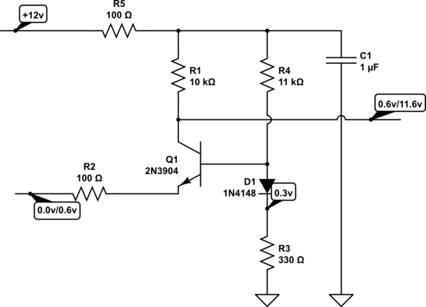
Consider thisl note the output has only a WEAK drive ability.

schematic

simulate this circuit – Schematic created using CircuitLab

The circuit will provide almost rail-rail output, using the impulse coil, which I assume is just about a short (< 100 ohms).

Or you could use a comparator that accepts inputs as low as GND. Some older ICs with PNP inputs perform quite well.

\$\endgroup\$
2
  • \$\begingroup\$ I have since, after significant research, learned that the impulse coil measures ~ 20 ohms, not the 433.5-586.5 ohms the repair manual states. I have learned from a cart forum that this is standard; that this value should produce a consistent .5 volt. Maybe in their world... Thanks to you folks that have suggested a comparator or signal amplifier. All above my head. \$\endgroup\$
    – user223205
    Commented Jun 11, 2019 at 17:48
  • \$\begingroup\$ I appreciate the schematic very much. I've not yet assembled it, hoping that I could find an igniter unit in my collection of parts. I found one that worked and the power supply wire immediately broke off flush with the unit. I am going to try and pick out the conformal coating and see what I can find. One more question: would the schematic as drawn operate a Darlington transistor? \$\endgroup\$
    – user223205
    Commented Jul 6, 2019 at 15:33

Your Answer

By clicking “Post Your Answer”, you agree to our terms of service and acknowledge you have read our privacy policy.

Not the answer you're looking for? Browse other questions tagged or ask your own question.