1
\$\begingroup\$

I design a system with several devices connected to 400kHz I2C interface with wires.

For now, I get shark fins instead of square waves, so I decrease pull up resistors value. The MCU, which drives the I2C communication is STM32F303, and its datasheet states: "I2C Fast mode plus (1 Mbit/s) with 20mA current sink". Does it mean that each pin (Data and Clock) can sink 20mA, and is it sustainable current or short peak value?

I am testing 500 Ohm resistors on my 3.3V system now. 3.3V/500Ohm = 6.6mA. I still get errors and the square is not good enough, I guess. May I go lower, 250 maybe?

Edit: I tried 340 Ohm resistors (around 10mA sink), and it is working for now. Almost no errors (1-2 per minute maybe, under load).

The system has motors, when motor load goes up, errors increase. I am using ferrite rings on the motor lines. Moving motor wires and I2C lines around does not seem to affect anything. I see some noise via oscilloscope. The only thing that affects error count for now is resistors values.

\$\endgroup\$
5
  • \$\begingroup\$ How long are the data lines? \$\endgroup\$
    – po.pe
    Commented Jul 15, 2019 at 9:17
  • \$\begingroup\$ The lines are 50 cm long. \$\endgroup\$ Commented Jul 15, 2019 at 9:19
  • \$\begingroup\$ BTW, what do you mean with "the square is not good enough"? I2C still works with non-perfect square wave signals. Are you sure the signal shape is the problem? \$\endgroup\$
    – Huisman
    Commented Jul 15, 2019 at 9:21
  • \$\begingroup\$ Lower the resistors I put, more square is the wave, and lower errors count becomes. \$\endgroup\$ Commented Jul 15, 2019 at 9:23
  • \$\begingroup\$ If squareness will stop influencing the errors count, I will start searching for other solutions. For now this is only thing I understand that affects the system. \$\endgroup\$ Commented Jul 15, 2019 at 9:25

2 Answers 2

3
\$\begingroup\$

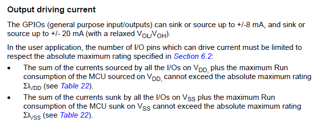
Yes, you could sink up to 20 mA on both I2C ports, but you have to keep the total current in mind.
It is explained in the chapter 6.3.14 I/O port characteristics:

enter image description here

Instead of lowering the pull-up resistors, you could also try if you can somehow lower the bus capacitance.

What do you mean with "the square is not good enough"? I2C still works with non-perfect square wave signals. Are you sure the signal shape is the problem?
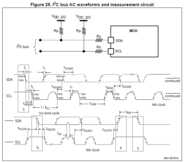
Check how non-perfect the squares are in the datasheet:

enter image description here

The only relevant about the signal is the I2C timings specification, given in Table 61 of the datasheet.

\$\endgroup\$
5
  • \$\begingroup\$ Thank you for the answer. What else can affect the communication? I added more info in the question. May be you can suggest something. \$\endgroup\$ Commented Jul 15, 2019 at 9:37
  • \$\begingroup\$ @RomanSimonyan Since moving around the wires doesn't seem to affect anything: is the 3.3V supply stable when the motors turn on? no spikes on it? \$\endgroup\$
    – Huisman
    Commented Jul 15, 2019 at 9:41
  • \$\begingroup\$ No nothing changes on the 3.3V line under load. \$\endgroup\$ Commented Jul 15, 2019 at 9:51
  • \$\begingroup\$ @RomanSimonyan Well, assuming you're measuring correctly (minimizing the probe loop as e.g. shown in electronics.stackexchange.com/questions/136123/…) try to stabilise the supply using input / output filters on the 3V3 supply as well as to the motor power supply. \$\endgroup\$
    – Huisman
    Commented Jul 15, 2019 at 10:03
  • \$\begingroup\$ I remeasured with minimal loop and the 3.3V line is very stable, no changes under load. \$\endgroup\$ Commented Jul 15, 2019 at 10:13
1
\$\begingroup\$

I've made good experience with increasing the bus capacitance:

With already-low pull-up resistors the load time of your 20cm wires is probably not the problem, but they catch a lot of noise from the motor lines. By adding parallel capacitors (from each bus line to ground, a few nF) you can make the lines more robust. The load time of the bus line should of course still match the I²C specifications. To approximate the load time you can start with t=R*C

I even reduced the load time by using constant current sources instead of pull-up resistors. I used one bipolar transistor per line to provide 20mA constant instead of the current from a resistor, which is decreasing while loading the capacitance.

\$\endgroup\$

Your Answer

By clicking “Post Your Answer”, you agree to our terms of service and acknowledge you have read our privacy policy.

Not the answer you're looking for? Browse other questions tagged or ask your own question.