0
\$\begingroup\$

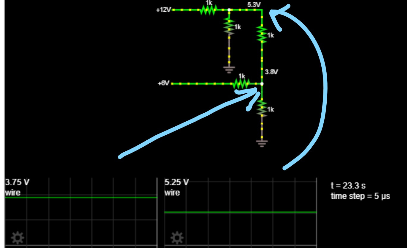
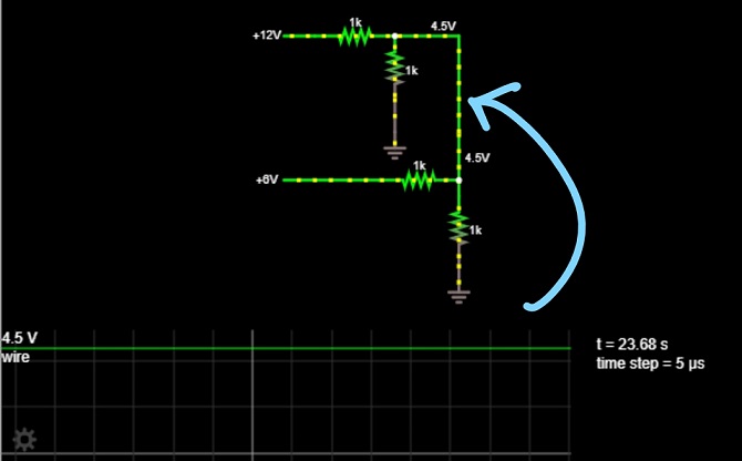
Could someone explain the voltage readings on the following "oscilloscopes" of the simulated schematics below:

(I understand the concept of a voltage divider but it seems something less straightforward is happening here)

To be clear, the top source is 12V DC and the lower one is 6V DC. All resistors have the same value.

The first one is simpler:

enter image description here

The second one adds a slight complication:

enter image description here

Sorry for the large size of the photos. I couldn't figure out how to resize them.

\$\endgroup\$

1 Answer 1

2
\$\begingroup\$

Strictly speaking, your circuits are not voltage dividers. The notion of a voltage divider, where the voltage at a point between two resistors is determined by the ratio of their resistances, works only if the resistors are in series. When elements are in series the current that flows through them is exactly the same.

In practice, you can use a voltage divider reliably as long as the current through the two resistors is nearly identical. That means that whatever you connect to the divider must draw much less current than what would flow through the resistors if nothing else was connected. As the difference in current increases the two resistors behave less and less like a "voltage divider".

In your circuits you have made connections that significantly change the current flowing through the resistors, so you can no longer consider these voltage divider circuits. To analyze these circuits on paper you need to use more sophisticated techniques, such as the mesh-current method or the node-voltage method.

\$\endgroup\$
5
  • \$\begingroup\$ hmm that makes A LOT of sense. The derivation of the voltage divider equation is indeed dependent on the same current flowing through the resistors in series... or at least nearly equal as you said. That explains a lot because I was using this question to understand a much more complicated circuit - I guess if the 6V source was something like a high impedance line level instead (\$\approx\$ 1.7V amplitude AC, 10k input impedance) then do you think we could treat the 12V source as effectively voltage divided? \$\endgroup\$
    – Andrew
    Commented Aug 23, 2019 at 12:00
  • \$\begingroup\$ It's not the impedance of the 6V source that matters, it's the size of the resistors you use with this source relative to the size of the resistors you use with the 12V source. Try making the two resistors connected to the 6V source be 100k instead of 1k. \$\endgroup\$ Commented Aug 23, 2019 at 12:05
  • \$\begingroup\$ When I alter the 6V source to be 1.7V (peak of audio signal, but keeping it DC) and then ADD a 10kohm resistor directly in front of that prior to the first 1k resistor, my junction voltage is now 3.932V (corresponding to the first schematic I posted). This nearly matches 4V which would be the Vout of the 12V source if it were voltage divided by the other two 1k resistors (a factor of 1/3 if you add the two resistors in parallel to the first resistor). Vout=1/3Vin. Does that make sense to you? \$\endgroup\$
    – Andrew
    Commented Aug 23, 2019 at 12:25
  • \$\begingroup\$ I've gotta simulate this in ltspice for complete confirmation \$\endgroup\$
    – Andrew
    Commented Aug 23, 2019 at 12:26
  • \$\begingroup\$ actually it doesn't quite check out because the relative sizes of the resistors do matter... hmm I wonder why this design uses 47k resistors... beats me. Thanks for your time \$\endgroup\$
    – Andrew
    Commented Aug 23, 2019 at 12:41

Your Answer

By clicking “Post Your Answer”, you agree to our terms of service and acknowledge you have read our privacy policy.

Not the answer you're looking for? Browse other questions tagged or ask your own question.