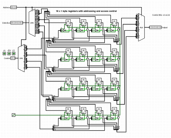
Consider the following. Let's say for simplicity sake I have an arrangement of 8 bit registers in a 4x4 matrix layout. I could easily use a Demux that has a 4 bit input select line for the addresses with an 8 bit data input and from that address line I can then easily select which of the 16 registers I want to access.
Instead of using a single Demux let's say I want to use 2 Demuxes to do the same thing except I want to designate one Demux to represent which row and another to represent which column.
I'll still be using the same 4 bit address line only I was thinking of using a wire splitter and using the 2 lower order bits of the address line for one demux and the two higher order bits of the address line for the other.
How would I be able to set up the arrangement of these Demuxes to access the appropriate row and columns of my matrix arrangement of registers?
Do I need to feed the data line into both demuxes? Would I need addition logic or muxes to combine the two lines? Or would a decoder help in this kind of situation? This is where I'm getting stuck at in my design decision.
I could use a single Demux however due to the limitations of Logisim my actual registers are 32 bits each and I have an arrangement of 8x8 registers for a total of 64 registers. I'm planning on using this as Cache for my CPU instruction register or instruction decoder.
If you need any more information than this or need any kind of diagrams or images let me know and I'll upload - post them upon request.
Here's my 16x1 byte register arrangement using a single Demux:

I want to make something similar however it won't be 4x4 as it will be 8x8 and the registers won't be 8 bits as they will be 32 bits and I was planning on using 2 Demuxes one for the row and the other for the column.
