2
\$\begingroup\$

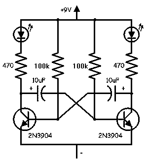
I know how to alternate between 2 LEDs using the simple 2 transistor, 2 capacitor and 2 resistor circuit here.

here is the circuit that i know how to do

My question, is if you add another transistor, capacitor and resistor, can you have it switch between 3 LED's, four LED's or even more? I am wanting a circuit that can flash each individual LED around a circle. And if so, how would I do this?

\$\endgroup\$
3
  • \$\begingroup\$ Is one-LED-at-a-time a requirement? \$\endgroup\$
    – jippie
    Commented Oct 25, 2012 at 18:45
  • \$\begingroup\$ Yes, because I will hook up 3 or four led's up to each output, and I don't want anymore then that hooked up. \$\endgroup\$
    – skyler
    Commented Oct 25, 2012 at 19:02
  • 2
    \$\begingroup\$ A microcontroller starts to look pretty attractive for this type of application for anything over a few 'channels', particularly since many micros can sink the necessary current without external drivers. \$\endgroup\$
    – HikeOnPast
    Commented Oct 25, 2012 at 19:31

3 Answers 3

1
\$\begingroup\$

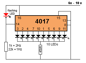
Or a decade counter: (you are free to arrange the ten LEDs in a circle if you wish.)

Led Chaser

\$\endgroup\$
3
  • \$\begingroup\$ There are also decade counter circuits that give you a count-up-to-N value, so you can pick however many leds you want \$\endgroup\$ Commented Oct 27, 2012 at 4:32
  • \$\begingroup\$ @EricGunnerson You are correct sir! However in that configuration I would replace the flashing LED with a bone fide clock circuit, maybe an old 555 Astable. \$\endgroup\$
    – rdivilbiss
    Commented Oct 27, 2012 at 17:58
  • \$\begingroup\$ bowdenshobbycircuits.info/4017-7.gif \$\endgroup\$
    – rdivilbiss
    Commented Oct 27, 2012 at 18:17
1
\$\begingroup\$

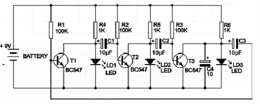
How about a simple phase shift oscillator?

phase shift oscillator

Although it looks easy to expand, from 4 stages upward two or more LED's will light up at the same time.

\$\endgroup\$
1
  • \$\begingroup\$ C4 is added to ensure the oscillator will start at power on. \$\endgroup\$
    – jippie
    Commented Oct 27, 2012 at 19:53
1
\$\begingroup\$

@skyler I know you're just starting out and are curious about this stuff, which I think we all want to encourage. So in that vein ....

What's cool about electronics is not just building it, but understanding it. And then once you understand it then extending it.

How your circuit above works is that the 100k resistors act as both a base resistor and as a charging path for the 10uF caps. Lets just say the right cap has 0 volts across it and the right hand transistor is on (it's collector is close to ground). the left hand resistor starts to charge up the RH cap. the LH transistor turns on, pulling the cap down, which then turns off the RH transistor. the RH resistor now starts to charge the LH cap and the process starts all over again.

With that knowledge you can see that simply adding/duplicating the cct's won't get the effect that you want as these are cross coupled. However, if you couple it in one direction A->B->C->A then you should get what you want.
\$\endgroup\$
4
  • \$\begingroup\$ Thanks, I do just want it to go A,B,C,A,B,C and not abcba so this should work \$\endgroup\$
    – skyler
    Commented Oct 25, 2012 at 19:58
  • \$\begingroup\$ Draw the circuit up and post it here first, I'm sure someone can give you feedback. It's cool to play with these things and learn them. While there are many ways to solve this issue, doing it this way is an excellent start to learning about transistors as switches. But always write up a little documentation, you'll thank yourself for it when you you've miswired something and can't see it. \$\endgroup\$ Commented Oct 25, 2012 at 20:05
  • \$\begingroup\$ I have the impression that your A->B->C->A solution is identical to the phase shift oscillator I mentioned, with the notice that it won't expand with the one-LED-at-a-time requirement. \$\endgroup\$
    – jippie
    Commented Oct 27, 2012 at 19:52
  • \$\begingroup\$ Yes, I was going to mention that! Thanks for bringing it up, but it's not identical in response given the non-linearity of the diodes etc. It should an exercise for @skyler to tell us what the difference is. \$\endgroup\$ Commented Oct 27, 2012 at 19:55

Your Answer

By clicking “Post Your Answer”, you agree to our terms of service and acknowledge you have read our privacy policy.

Not the answer you're looking for? Browse other questions tagged or ask your own question.