1
\$\begingroup\$

I found the perfect circuit for a flashing pattern, only I need two LED's to alternate with this pattern. I attached the flashing circuit found on YouTube, copyright of GeoProgrammer. So basically, first LED would flash, then the second then the first again and so on. Making it possible to regulate the switching rate would be great. It is for a scale model. All help very much appreciated in advance.enter image description here I hope I can express better what I mean by showing two GIF's. First shows two LED's alternating. Simply on off. The second GIF shows how I would like each LED to light up, instead of just turn on and off. i2-download.imgflip.com/4rc8d7.gif i2-download.imgflip.com/4rc6lt.gif

schematic

simulate this circuit – Schematic created using CircuitLab

\$\endgroup\$
11
  • \$\begingroup\$ Are you sure you've drawn that right? I fail to see how this could possibly work. \$\endgroup\$ Commented Dec 19, 2020 at 20:01
  • \$\begingroup\$ what is your question? \$\endgroup\$
    – jsotola
    Commented Dec 19, 2020 at 20:11
  • \$\begingroup\$ That circuit cannot work, Geoprogrammer uses an LED with an internal oscillator to control the timing of their 3-led blinker, for a two LED blinker where you control the timing use the two transistor astable multivibrator circuit. \$\endgroup\$ Commented Dec 19, 2020 at 23:44
  • \$\begingroup\$ build-electronic-circuits.com/astable-multivibrator \$\endgroup\$
    – Mattman944
    Commented Dec 20, 2020 at 0:33
  • \$\begingroup\$ I saw the video from GeoProgrammer showing the LED slowly coming on, up to a bright flash and then fading. He showed the schematic, I have no idea if it is correct, beeing an electronics dummie. I would like to have two LED's flashing alternative in that way, so LED 1 slowly coming on, up to bright flash and then fade, then LED 2 same, then LED 1 again. Hope I'm explaining it clearly. Thanks for your time. \$\endgroup\$
    – DIB
    Commented Dec 20, 2020 at 8:32

2 Answers 2

2
\$\begingroup\$

This is less trivial then one might think. This is my stab at it, tested on breadboard with VCC = 9V.

schematic

simulate this circuit – Schematic created using CircuitLab
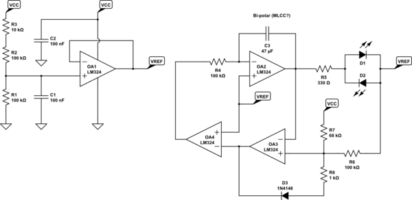
OA1 is a simple unity gain buffer used to create a reference voltage a bit below VCC/2. (In order to compensate for the fact that the LM324's outputs can swing closer to ground then to VCC).

OA2 is a integrator that slowly integrates upwards or downwards in order to create the fade effect.

OA3 is configured as a comparator with hysteresis in order to change the direction of the integrator when it reaches it minimum or maximum target voltage. Resistor divider R6/R7 sets the upper limit when integrating upwards while R8 is added into the mix trough D3 when integrating downwards.

OA4 simply inverts the output of OA3.

Note that C3 has to be a bipolar capacitor. Depending on the desired speed you might need a somewhat large value (the values shown result in about 15 seconds / cycle). A simple solution would be a MLCC SMD capacitor. You can play with the values of R4/C3 to change the speed.

For larger operating voltages make sure to adjust R5 to keep the LED current in check. (<= 20mA should be fine for the LM324).

\$\endgroup\$
1
  • \$\begingroup\$ You guys! Never expected to have such good and fast response. I'm a bit embarrassed to admit that I have no electronics knowledge at all, so some of the explanation goes way over my head, but fascinating none the less to see you guys accepting "the challenge". Many many thanks, I'll have a go at it coming holidays and will keep you posted. \$\endgroup\$
    – DIB
    Commented Dec 20, 2020 at 17:51
0
\$\begingroup\$

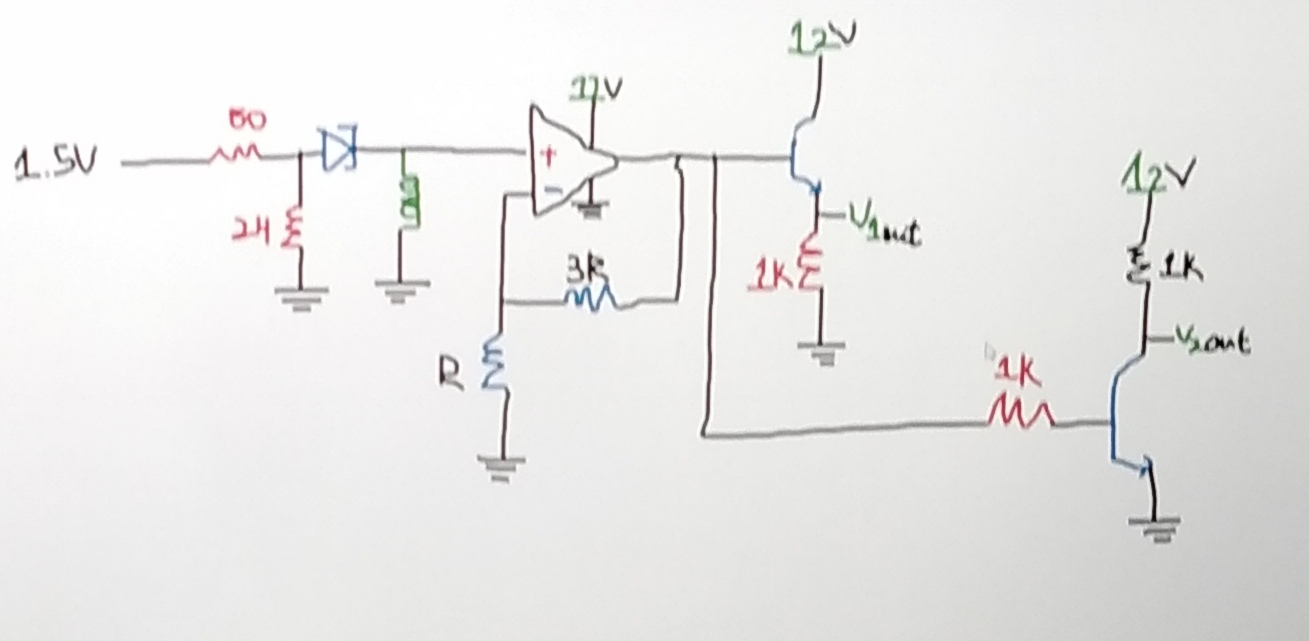
You can try this circuit I just invented. Thanks Mattman for giving me the challenge.

enter image description here

Now if you want to understand how it works you need to do reading on relaxation oscillators opamps and transistors.

\$\endgroup\$
1
  • \$\begingroup\$ You guys! Never expected to have such good and fast response. I'm a bit embarrassed to admit that I have no electronics knowledge at all, so some of the explanation goes way over my head, but fascinating none the less to see you guys accepting "the challenge". Many many thanks, I'll have a go at it coming holidays and will keep you posted. \$\endgroup\$
    – DIB
    Commented Dec 20, 2020 at 17:51

Your Answer

By clicking “Post Your Answer”, you agree to our terms of service and acknowledge you have read our privacy policy.

Not the answer you're looking for? Browse other questions tagged or ask your own question.