0
\$\begingroup\$

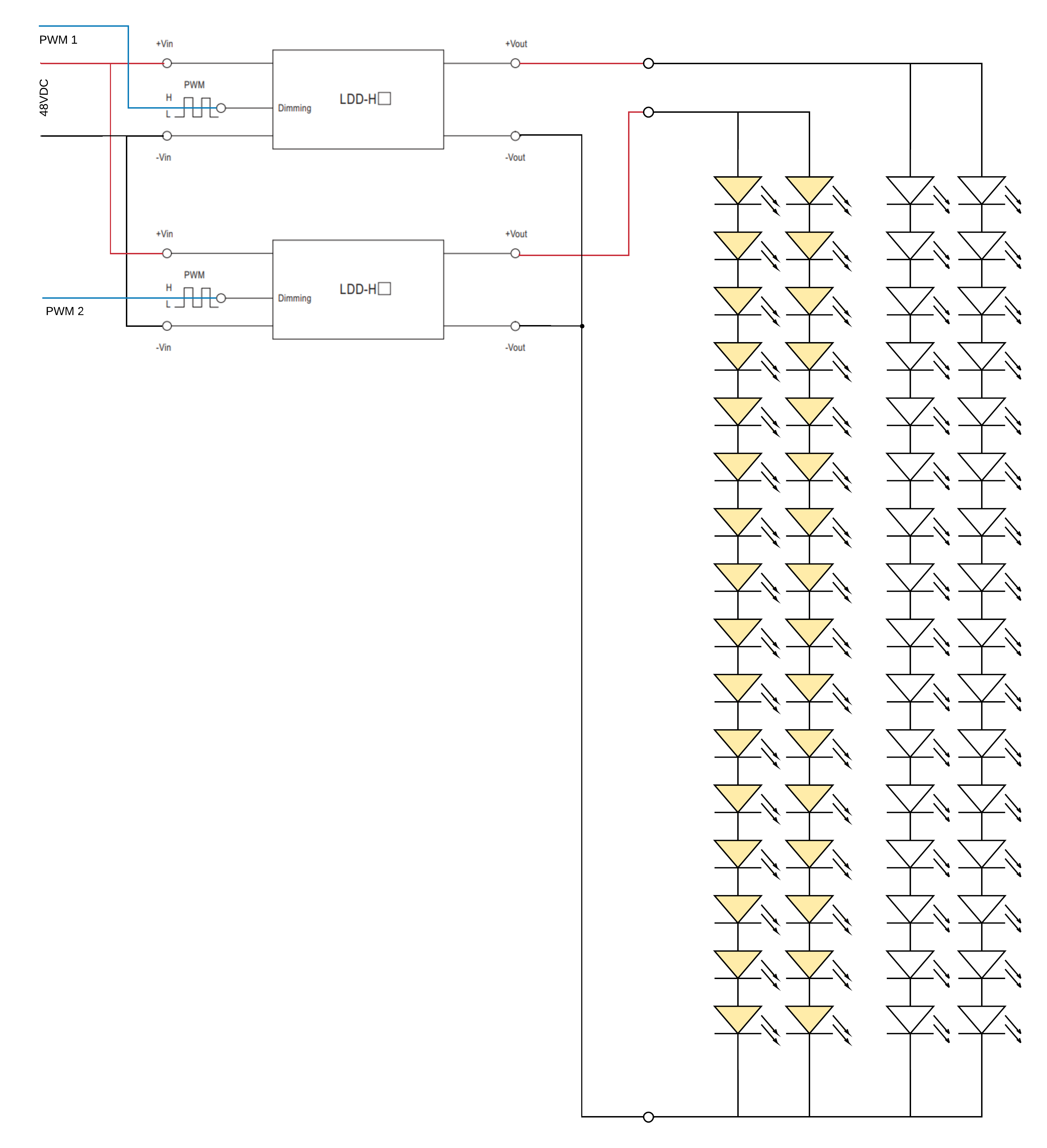
I'm using these Mean Well LDD-H DC-DC constant current step-down LED drivers to drive these LEDs.

What I'm seeing is that when the -Vout terminals of the drivers are connected together, both LED strips start being driven in sync (as if the PWM inputs are connected).

If is use a separate ground for each driver-strip pair, it works as expected.

Why is that happening?

enter image description here

Closely related to this question, but with more specifics.

\$\endgroup\$
1
  • \$\begingroup\$ To elaborate on the good answers below: It's very typical for these devices to be "common positive", i.e. the input and output positive rails are connected together (rather than the negative rails, as you might expect, which are actually being switched.) This is because of the asymmetry in MOSFETs -- NMOS is cheaper than PMOS (all other things being equal), which makes switching the negative rail easier. \$\endgroup\$ Commented Sep 4, 2019 at 22:48

2 Answers 2

3
\$\begingroup\$

enter image description here

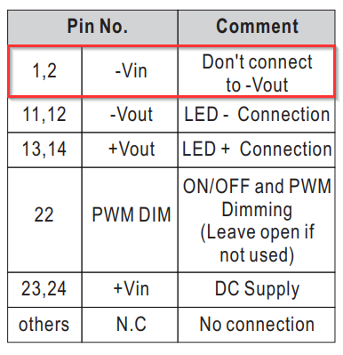
Figure 1. The datasheet suggests that there is no isolation between input and output.

schematic

simulate this circuit – Schematic created using CircuitLab

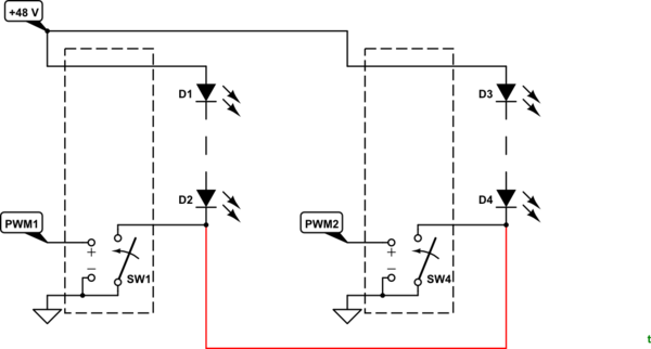
Figure 2. You have added the red link.

It should be clear from Figure 2 that you have "ORed" the power supply switchers and whichever one turns on will turn on both strings of LEDs. Bad idea!

\$\endgroup\$
2
\$\begingroup\$

The -Vout is probably part of the control loop and is not 'common'.

Note on page 2 of the datasheet that they say about -Vin, "Don't connect to -Vout". This gives you a clue that -Vout is not common/ground.

\$\endgroup\$

Your Answer

By clicking “Post Your Answer”, you agree to our terms of service and acknowledge you have read our privacy policy.

Not the answer you're looking for? Browse other questions tagged or ask your own question.