1
\$\begingroup\$

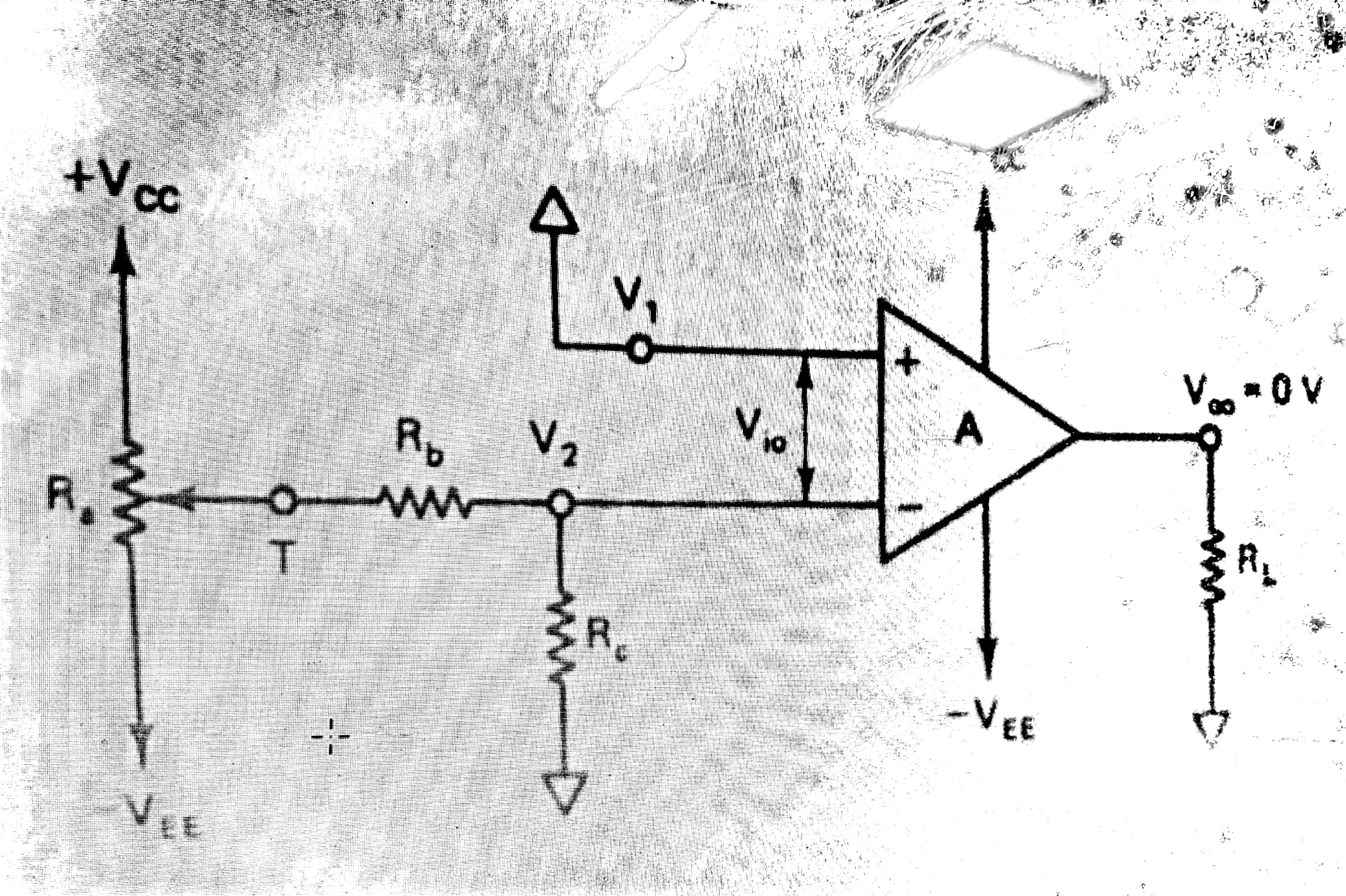
While reading a book on opamps I came across this output offset voltage compensating circuit. enter image description here
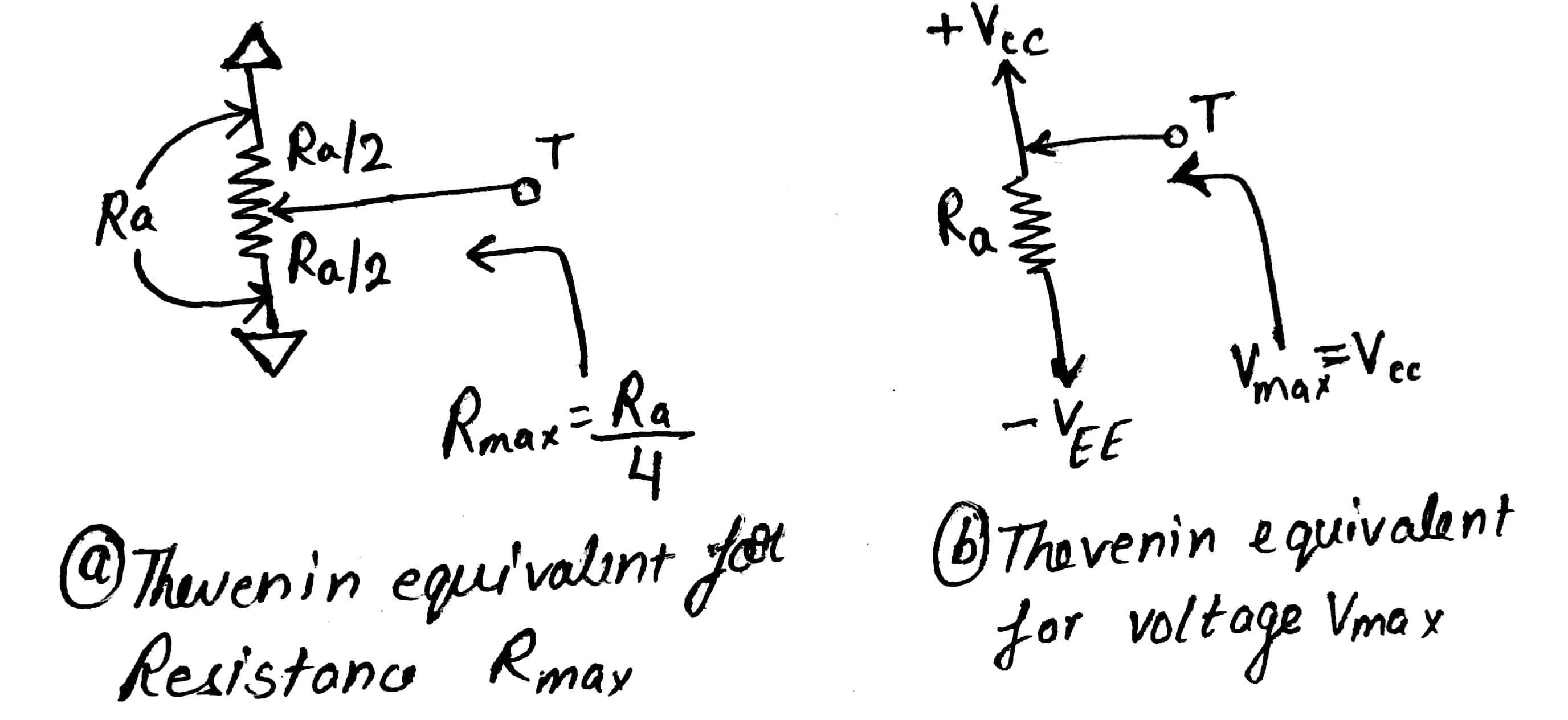
They used thevenin's circuit looking at Ra from point T: enter image description here
Then they converted a part of the first circuit the this: enter image description here
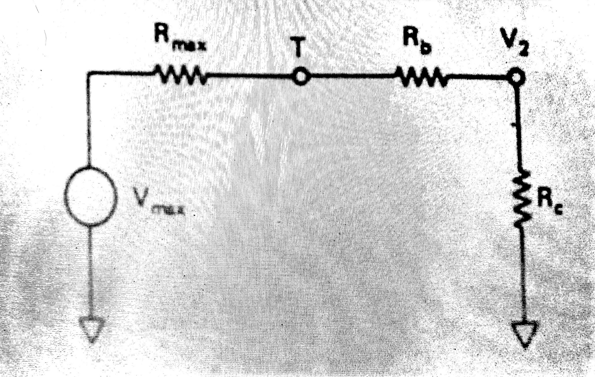
But what I don't understand is how can the given circuit can have both resistance Rmax as well as voltage Vmax at the same time? Why have they shown both the things together in the same circuit. Like if the resistance were Rmax, voltage would have been zero at point T. Can anyone explain please!

Thanks!

\$\endgroup\$
2
  • 1
    \$\begingroup\$ This method is doing things more complicated than they need to so in my opinion this is a very bad example to show DC offset compensation. What they're doing is using a resistive divider circuit to add/subtract a DC voltage to the - input. It is easier to explain if this voltage was applied to the + input as then it will not interfere with the input signal. Using the opamp in open-loop (no feedback) like that only works in theory, try this with a real opamp on a bench and you'll notice how it is impossible to get the output at 0 V. Noise and thermal effects will prevent that. \$\endgroup\$ Commented Sep 23, 2019 at 6:25
  • 1
    \$\begingroup\$ If you want to learn about opamps I recommend reading the free ebook, opamps for everyone: web.mit.edu/6.101/www/reference/op_amps_everyone.pdf and also watch the videos made by Dave from the EEVBlog: youtube.com/… \$\endgroup\$ Commented Sep 23, 2019 at 6:27

1 Answer 1

0
\$\begingroup\$

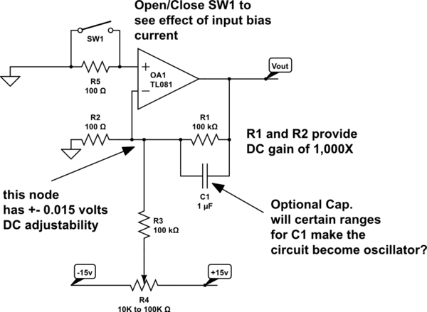
consider this

schematic

simulate this circuit – Schematic created using CircuitLab

\$\endgroup\$

Your Answer

By clicking “Post Your Answer”, you agree to our terms of service and acknowledge you have read our privacy policy.

Not the answer you're looking for? Browse other questions tagged or ask your own question.