4
\$\begingroup\$

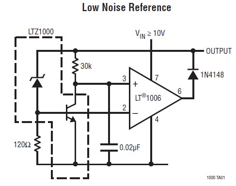
This circuit is from the datasheet of the famous voltage reference LTZ1000. Can anyone explain how the circuit works in detail? Particularly the OpAmp.

Schematic

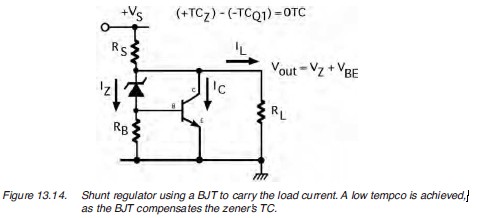
I find another similar circuit without Op-amp using in the book "Current Sources & Voltage References" by Linden T. Harrison.

enter image description here

I think there are something similar. My question now is what we can benefit from the op-amp ?

\$\endgroup\$

3 Answers 3

5
\$\begingroup\$

The zener and 120 ohm resistor form one arm of a bridge. The 30K resistor and BJT form the other arm. The bridge will be balanced when the transistor \$V_{CE}\$ is the same as the \$V_{BE}\$. The op-amp forces said bridge into balance.

Under balance conditions, the current through the zener is about 5mA (held constant). The transistor \$I_C\$ is about 220uA.

The output voltage is the zener voltage plus \$V_{BE}\$. At the voltage the manufacturer has chosen for the buried zener (7.2V - \$V_{BE}\$), the positive temperature coefficient of the zener matches the negative temperature coefficient of \$V_{BE}\$ , so the overall temperature coefficient is close to zero and the output voltage is nominally 7.2V.

In the old days (before high-performance IC references became common), one of the best references you could buy was the 1N821A (and its cousins), which have a diode internally in series with a zener (you can tell this indirectly from the data sheet because the 'reverse' current is blocked by the diode to a maximum of a few uA).

Of course in the venerable LTZ1000, the tempco is usually further improved by stabilizing the die temperature at a temperature above ambient using the internal heater and temperature sensor.

\$\endgroup\$
3
  • \$\begingroup\$ So compared to the zener diode in series with BJT (with base and collector shorted) I can see one benefit of this circuit: Ic does not go through the zener therefore we can control its current more precisely. \$\endgroup\$ Commented May 12, 2014 at 19:18
  • \$\begingroup\$ Yes, the op-amp forces the bridge to balance, then what we can benefit from the balanced bridge ? \$\endgroup\$
    – diverger
    Commented May 14, 2014 at 0:56
  • 1
    \$\begingroup\$ The benefit? The current through the zener is constant, the \$I_C\$ on the transistor is almost constant, so the voltage at the op-amp output is a buffered version of the zener voltage plus \$V_{BE}\$ and is thus properly temperature compensated and constant with supply voltage changes. \$\endgroup\$ Commented May 14, 2014 at 1:47
4
\$\begingroup\$

The zener diode has a positive temperature coefficient of, according to the data sheet, \$+\frac{2mV}{^\circ C}\$ while the base-emitter junction has a negative temperature coefficient of \$-\frac{2mV}{^\circ C}\$

Assuming the op-amp has negative feedback, the input terminals have the same voltage. Since the base and collector of the transistor are connected across the input terminals, this transistor is essentially a diode connected BJT (base and collector have the same voltage).

Then, assuming the base current is insignificant, the output voltage is, by KVL

$$I_{ZD}\cdot 120 \Omega + I_E \cdot 30k \Omega $$

For the output voltage to be constant with temperature, we must have that

$$\frac{\partial I_{ZD}}{\partial T} \cdot 120 \Omega + \frac{\partial I_E}{\partial T} \cdot 30k \Omega = 0$$

Clearly, this requires that temperature coefficients for the zener diode and transistor have opposite signs.

The choice of resistor values depends on a number of process dependent variables that are beyond the scope of this answer.
\$\endgroup\$
1
  • \$\begingroup\$ Thanks. I know the basic temperature compensation. But just want to know why use the OP? What we can benefit from the Op-Amp? \$\endgroup\$
    – diverger
    Commented May 14, 2014 at 0:59
0
\$\begingroup\$

The Op Amp feeds the buried zener and increases dramatically the PSRR and improves line regulation - it creates an ultra stable LDO of 7.2V feeding the buried zener and the base-emitter junction. The buried zener current is defined by the 120Ω resistor and collector current defined by 30kΩ resistor - this along with the heater temperature creates the ideal bias point where the TC of the buried zener is opposite to the TC of the Base Emitter junction of Q1. In practice one will need to trim the heater temperature to fine tune this TC zero spot with R4:R5 in LTZ1000A datasheet, the nominal ratio for R4:R5 = 12,5:1 for LTZ1000A and 12:1 for LTZ1000.

\$\endgroup\$
1
  • \$\begingroup\$ I know this Op Amp working in the negative feedback mode, can you give some explanation about why i negative feedback, not positive? \$\endgroup\$
    – diverger
    Commented Sep 5, 2014 at 0:45

Your Answer

By clicking “Post Your Answer”, you agree to our terms of service and acknowledge you have read our privacy policy.

Not the answer you're looking for? Browse other questions tagged or ask your own question.