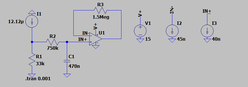
I have a current source with RC filter at the input of an LM324 op-amp configured as a buffer. The Input Biasing Current is 45nA and the Offset Current is 5nA for the LM324.The input resistor is 750k and normally a 750k resistor in the feedback loop would balance the inputs. With the output connected directly to IN- there is about a 30mV difference between the input and the output, where the input is about 400mV. However to get the circuit to provide a gain of 1 I doubled the feedback resistor to 1.5Meg. The result is much better and the output error is much smaller. Why is it that double the resistor was needed here and not 750K?
Also I am trying to simulate this behavior in LTSpice using the circuit below and have included the offset input currents. However a direct connection from output to IN- gives a gain of 1 and does not indicate real life results. is there a better way to model this?
Thanks.
Edit 1:
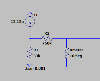
Meter at IN+ creating a voltage divider with R2 and creating a voltage drop. When the same meter is used to measure the output the voltage divider disappears. Tried with 2 meters simultaneously and input and output were closer. Still has the voltage drop, but they are the same.


