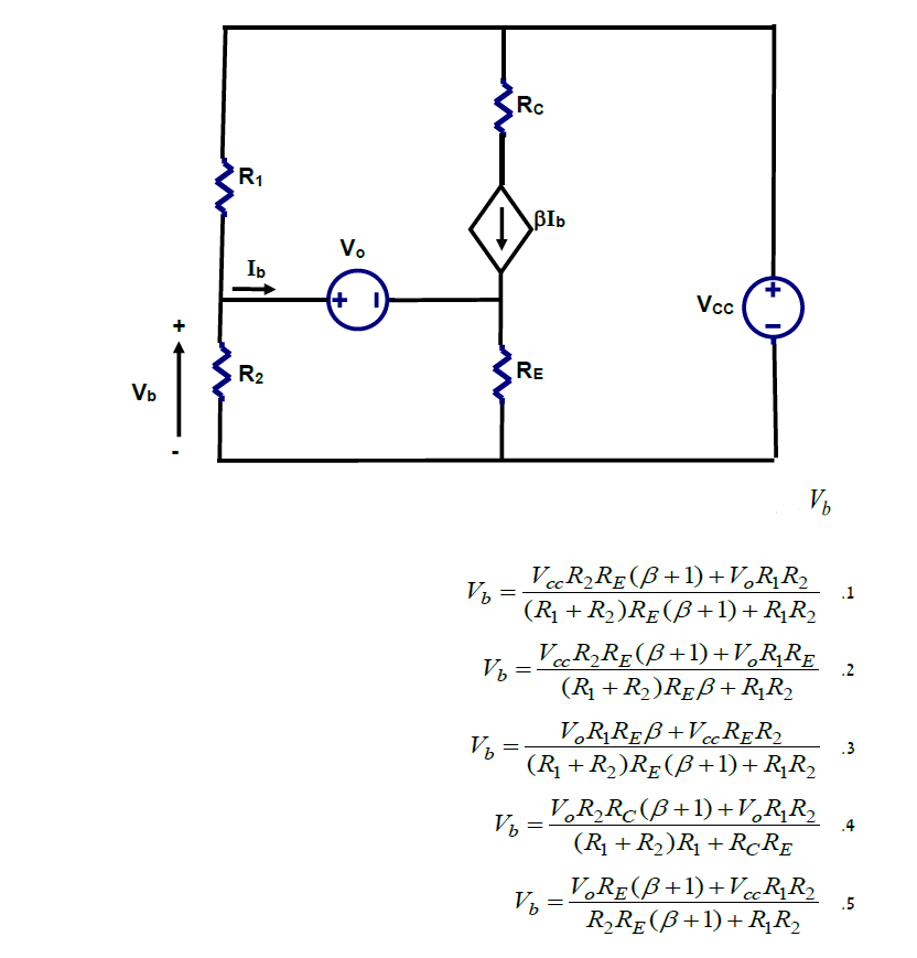
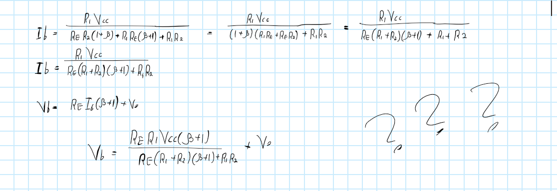
I've been wasting my time on this problem and I did get really close to a solution which took a long time but still wasnt able to get the solution. I was wonderting that I might approach this problem in the wrong way which is the main thing that bothers me. The question was to find the voltage Vb I tried both mesh and node analysis also tried super/node/mesh. below is as far as I got to a solution. I would be glad if someone can enlighten me on how to approach this kind of question as I'me having some trouble with those. Thanks.
-
\$\begingroup\$ I'm not going to give you the exact solution. Since this is a test question, it's better be worked out wisely without going through a bunch of equations and wasting time and energy. And I guess that's not the purpose of the asker to do all the math either. Anyway start off by setting RE=infinite. In this case Ib ends up being 0, and so Vb simple becomes R2/(R1+R2)Vcc, which only option (1) gives you that for RE=infinite. \$\endgroup\$– dirac16Commented Dec 28, 2019 at 15:01
-
\$\begingroup\$ Wow, thank you so much! you've opened my mind to another way of solving problems such as that which I'm sure will be far more useful then solving directly. Thanks again! \$\endgroup\$– Or-el EdriCommented Dec 28, 2019 at 15:50
-
\$\begingroup\$ Most of us who have tinkered with discrete components in practice spot directly that this is equivalent with classic, at least say 65 years old bipolar transistor biasing problem. Even the used letters are the same as usually. It helps to see that the right selection must be 1. Otherwise assuming beta=infinite, or as already said, RE=infinite leads to impossibilities. \$\endgroup\$– user136077Commented Dec 28, 2019 at 16:16
-
\$\begingroup\$ electronics.stackexchange.com/questions/471906/… \$\endgroup\$– G36Commented Dec 28, 2019 at 22:31
1 Answer
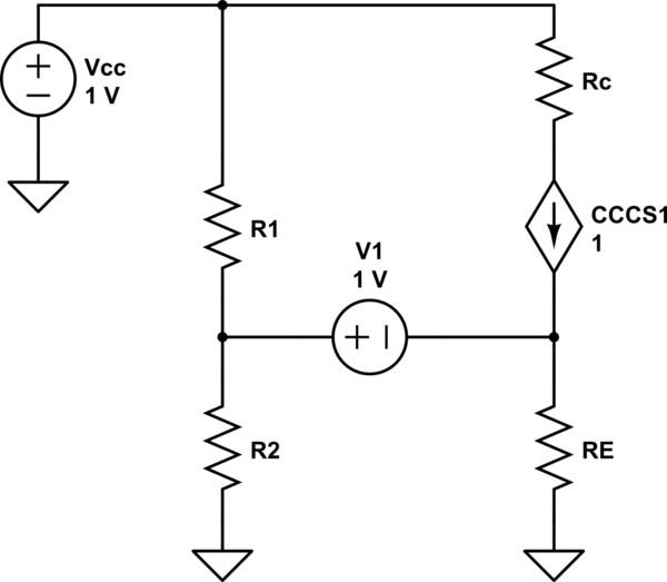
Put the bottom common node at ground; then \$V_b \equiv V_{R_2}\$. The circuit becomes:

simulate this circuit – Schematic created using CircuitLab
KVL says: \$V_b=V_0+R_EI_E\$ where \$I_E=I_B+(1+\beta)I_B=I_B(1+\beta)\$ and \$I_B=I_{R_1}-I_{R_2}=\frac{Vcc-V_b}{R_1}-\frac{V_b}{R_2} \$. Putting it all together with a bit of trivial maths readily gives (I'll skip steps): $$V_b+V_b(1/R_1+1/R_2)R_E(1+\beta)=V_0+\frac{V_{cc}R_E(1+\beta)}{R_1} \\V_b\left( \frac{R_1R_2+(R_1+R_2)R_e(1+\beta)}{R_1R_2}\right)=V_0+\frac{V_{cc}R_E(1+\beta)}{R_1}$$ solve for \$V_b\$ and you're done.


