1
\$\begingroup\$

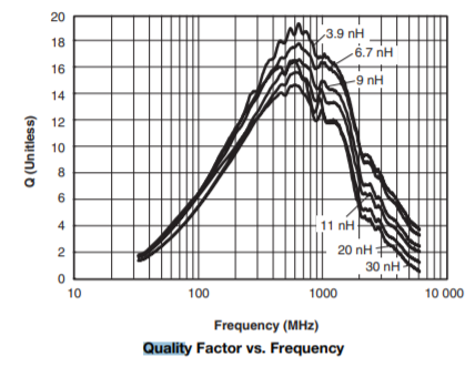
I have seen that some electrical components (which contain R,L,C elements) datasheets shows the curve of the quality factor Q with respect to frequency, and not simply its value at the resonance frequency. For instance, this is the curve we find on this inductor datasheet of an high frequency inductor:

enter image description here

Now, the definition of the quality factor is this one:

enter image description here

At resonance the energy stored in the equivalent RLC circuit of the component may be evaluated as the maximum energy stored in the inductance or also as the maximum energy stored in the capacitance during a period, since at resonance both quantities are equal. But how we evaluate the energy stored for a generic frequency? I'd say that in general, the energy stored in the magnetic field is different from that stored in the electric field, if we are not working at resonance.

\$\endgroup\$
1
  • \$\begingroup\$ If your question is: "But how we evaluate the energy stored for a generic frequency?" do change the title because everyone is focussing on the quality factor \$\endgroup\$
    – Huisman
    Commented Dec 29, 2019 at 20:45

2 Answers 2

1
\$\begingroup\$

You're using a definition from wikipedia which explicitly has failed verification:

wikipedia screenshot

Obviously, tread carefully if you use wikipedia, and twice so if the authors of the wikipedia page disagree on something. Generally, the quality of wikipedia on fundamental EE is often not very good. Do not use Wikipedia as only source! (that goes for anything, basically, but it really applies to wikipedia, and students these days are taught that wikipedia is of mixed quality.)

So, I'd not pay any attention to that definition unless it's especially useful to me. I'm too lazy to check whether that formula actually is correct (i.e. means the same as the usual definitions of quality factor).

Instead, use the much more common formula that relates the losses to the energy oscillating in and out of an inductor (that we model with a series parasitic resistance):

$$Q_L(f) =\frac{X(f)}{R} = \frac{2\pi f L}{R}$$

with \$f\$ being the frequency, \$L\$ the inductance at that frequency (that's not a constant in real materials) and \$R\$ representing ohmic losses.

\$\endgroup\$
10
  • \$\begingroup\$ I think you should add the equation applies to a series RLC circuit \$\endgroup\$
    – Huisman
    Commented Dec 29, 2019 at 18:00
  • \$\begingroup\$ Series RL; but yes. \$\endgroup\$ Commented Dec 29, 2019 at 18:02
  • \$\begingroup\$ Why series RL and not RCL? For series RCL, at resonance \$Q = X_C/R = X_L/R \$. \$\endgroup\$
    – Huisman
    Commented Dec 29, 2019 at 18:09
  • 1
    \$\begingroup\$ Marcus I dont see why there is so much fuss with Wiki accuracy, Q has always been well defined for 1st order elements as @Huisman just did which is the same as D.F. =1/Q but for 2nd order elements (LC) the Q=VAR/Pd ratio must be used, then is still accurate for 1st approximation VAR=I(f)^2*Xc(f) \$\endgroup\$
    – D.A.S.
    Commented Dec 29, 2019 at 19:02
  • \$\begingroup\$ The Q of an imperfect inductor is XL/R. The Q for a much more perfect capacitor in parallel might as well be infinity in comparison AND, therefore the net Q is basically XL/R. +1 for this answer.. so, use the more sensible formula for Q. \$\endgroup\$
    – Andy aka
    Commented Dec 29, 2019 at 19:37
0
\$\begingroup\$

There are valid complaints on Q values due to many dependancies and differences.

Not only are they dependent on excitation frequency, DC current but also the test method and instrument which may lead to different values.

The simple Q values such as those dependent on a 1st order component are very useful. Q=1/DF i.e. Dissipation factor in low ESR e-caps

But for 2nd and higher order components such as this coplanar coil the ratio of reactive power is complex to real power dissipated.
(Wiki definition is correct in question)

Designers should ask supplier to furnish use of impedance analyzer test results
= s-parameters , to eliminate correlation issues for complex RF characteristics

e.g. a coil that is 5% tolerance at one frequency could be 10% at another.

TYPICAL VARIATIONS 

INSTRUMENT FREQUENCY     INDUCTANCE
HP4342A Q meter 25 MHz     682.3 nH
HP4192A 0.130 MHz          607.0 nH
HP4192A 10 MHz             592.7 nH
Booton 62AD 1 MHz          594.0 nH
Tektronix LC130 0.130 MHz 1300.0 nH
HP4191A 100 MHz           1065.0 nH

comments

Although we know Q=2πfL/R these coils also have variable L & R from skin effects. This peak is not the typical SRF you expect as they claim that SRF > 5GHz.

\$\endgroup\$

Your Answer

By clicking “Post Your Answer”, you agree to our terms of service and acknowledge you have read our privacy policy.

Not the answer you're looking for? Browse other questions tagged or ask your own question.