0
\$\begingroup\$

I am creating a small application in which on detecting the water the Buzzer will ring. But right now I am testing with LED instead of Buzzer.

Raindrop Sensor datasheet link: https://components101.com/sensors/rain-drop-sensor-module

I am using a Raindrop sensor: enter image description here

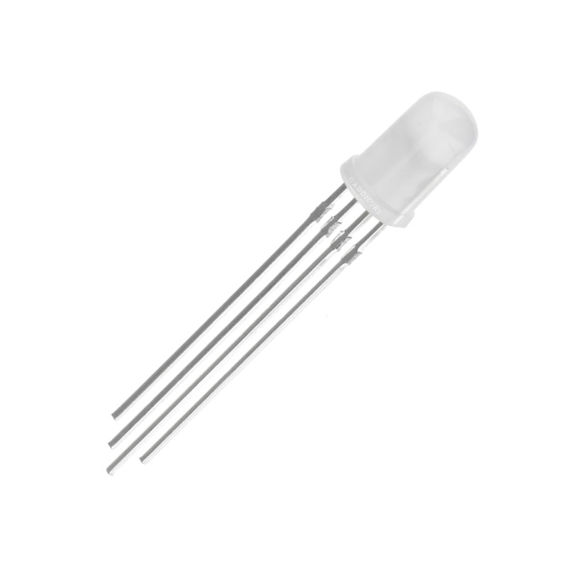
And RGB LED: enter image description here

I don't need any MCU in this project. I connected the sensor to the 5V and GND and connected the A0 (Analog Pin) to the Positive of LED.

Note: 5V and GND were supplied from Arduino UNO

Like this:

schematic

simulate this circuit – Schematic created using CircuitLab

But LED turns on as soon as I connect power to the circuit. And when I drop water on the sensor LED turns OFF. Opposite of what I want. So I thought of using a transistor as a switch to turn LED ON on detecting water.

Below is my circuit:
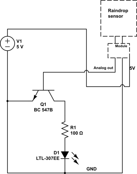
schematic

simulate this circuit

But this isn't working at all. Any guide on how can I get it to work with or without transistor.

New Try

schematic

simulate this circuit

\$\endgroup\$
18
  • \$\begingroup\$ I suggest that you have a look at how others use a transistor and a LED with a module (or microcontroller). Note how your circuit is significantly different from what everyone else uses. A transistor is like a switch, if your transistor/switch is closed, you're shorting the LED, how can that ever work? You don't have a resistor in series with the LED, that will destroy the LED and transistor. Without details about the "Module" it is impossible to judge if what you want is even possible. \$\endgroup\$ Commented Feb 3, 2020 at 7:43
  • \$\begingroup\$ @Bimpelrekkie The module is nothing but the device you see in the first picture of the Raindrop sensor in blue color. LED is connected with a 100-ohm resistor to the collector of the transistor. So what to do? can you please provide a solution using the schematic diagram. \$\endgroup\$
    – Lucifer
    Commented Feb 3, 2020 at 7:50
  • \$\begingroup\$ LED is connected with a 100-ohm resistor to the collector of the transistor. No it is not, I don't see it in the schematic so it is not. If you're that inaccurate with your schematic then there's no point trying to help you. What have you learned from searching for "switch led with transistor" in Google and selecting the "Images" tab? You're not the first to try this. There are plenty of examples to be found. I'm not going to "hold your hand" and explain you how to connect everything. I can provide working schematic but that costs $50. Finding your own is free. \$\endgroup\$ Commented Feb 3, 2020 at 7:58
  • \$\begingroup\$ Share the datasheet of the sensor. The image alone seldom helps. What is the analogue out drive strength? \$\endgroup\$
    – User323693
    Commented Feb 3, 2020 at 8:45
  • \$\begingroup\$ @Bimpelrekkie I forgot to add it in. I will update it right now. And yes I have searched and found the schematics of LED switching using a transistor and I am right now gonna try that and check. And I just asked for a reference and you have given it to search but your saying way is kind of rude. And I know I am not the first but on searching what you find is methods to do with different things and here people shares out of box things and share their personal experience. Not all the circuits in the image section are workable according to my application. I am not saying you are wrong. \$\endgroup\$
    – Lucifer
    Commented Feb 3, 2020 at 9:56

1 Answer 1

1
\$\begingroup\$

I would like to help you with your problem. Please consider that we all do it for mutual learning and helping each other for free. Learning by doing is the best way to learn. Consider the comments and questions as a good wayguide to address the problem and learn.


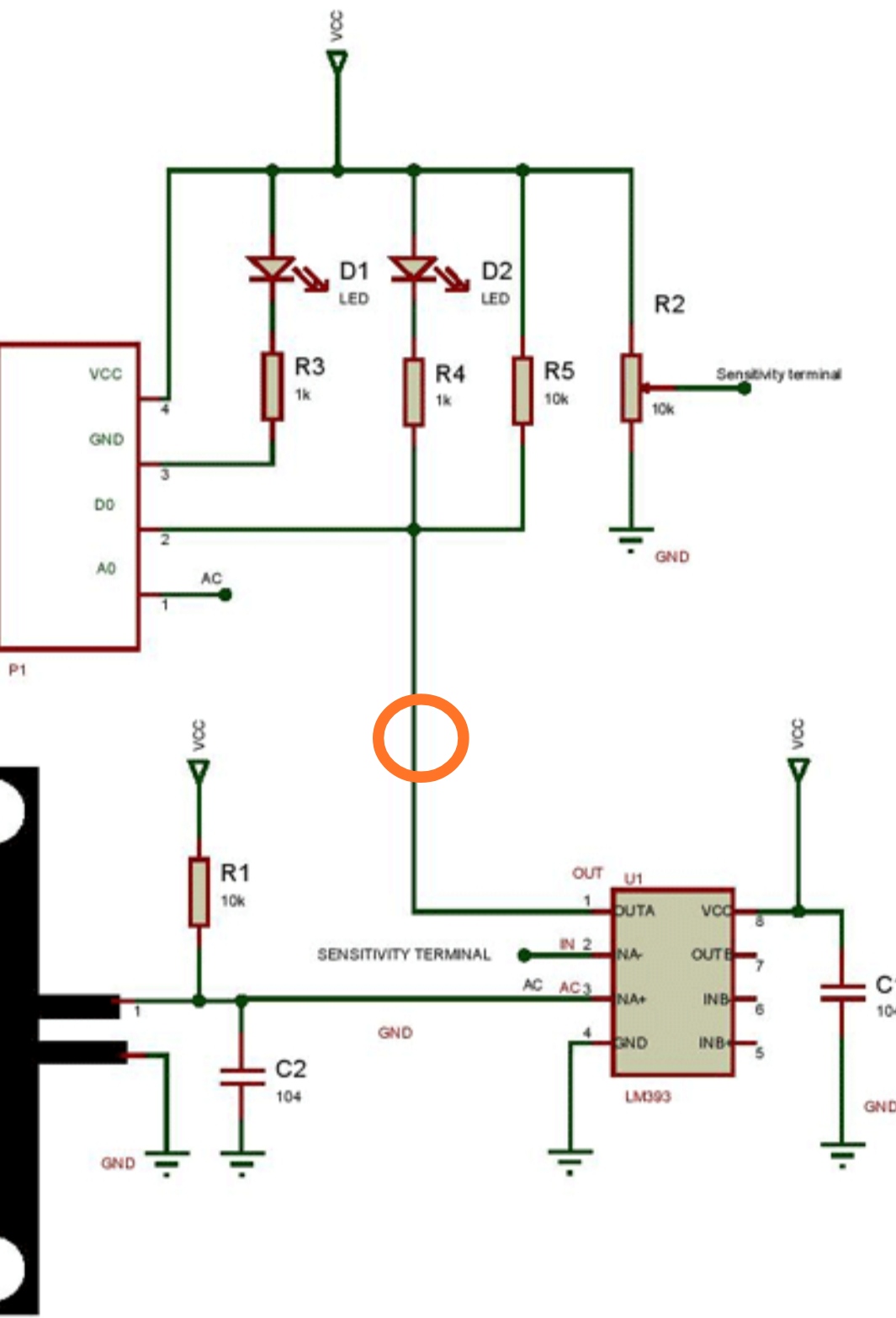
Please use the digital output pin for the module.

As per the schematics, it is the output of the comparator. You don't need a microcontroller to use the digital output pin.

Below is an example circuit I recommend.

  1. The digital output of the module can be connected to the base of the Q1.
  2. The three LEDs can be replaced by your single LED. Forget the tricolor LED. Please use a simple one for now.
  3. When there is no water (rain), the digital output of the comparator will be high. This will turn on the Q1. This will turn off the MOSFET M1. Hence the buzzer (LED) will be off.
  4. When there is rain, the Digital output will go low. This will turn off the BJT Q1. MOSFET gate source vorlage is high enough to turn it on. Bizzer (LED) should be on now.
  5. With a multimeter please check the behaviour of Digital Output pin D0 to make sure it is toggling. Use the available options to tune your circuit.
    enter image description hereenter image description here
\$\endgroup\$
5
  • \$\begingroup\$ Yes, you are right. I learn here more than I learn about searching and getting wrong understanding. I don't have a MOSFET with me so I have to wait till it gets delivered I have ordered it. And also I have checked the voltage output of the Digital output and analog output of the sensor they were: Analog pin of the sensor is 4.99~5V and when I drop water on the sensor the voltage drops to 0.10-0.12V. Then I checked the voltage on the digital pin it was 0.10-0.12V with and without water on the sensor. \$\endgroup\$
    – Lucifer
    Commented Feb 4, 2020 at 7:27
  • \$\begingroup\$ You can swap it with a npn BJT as well. MOSFET is good for higher currents. For LED BJT will do. M1 can be same as Q1 \$\endgroup\$
    – User323693
    Commented Feb 4, 2020 at 7:29
  • \$\begingroup\$ @Lucifer the analog and digital outputs were fine? \$\endgroup\$
    – User323693
    Commented Feb 4, 2020 at 7:30
  • \$\begingroup\$ I was not able to check current because my multimeter is broken and it just checks voltage, resistance, and connectivity. I have to buy one more NPN BJT. I will order a pack of BJT and MOSFET. \$\endgroup\$
    – Lucifer
    Commented Feb 4, 2020 at 7:31
  • \$\begingroup\$ Analog output was fine but was in reverse I think. And I don't have experience with digital output without a microcontroller so I can't say for sure. The output of the digital pin was just fluctuating between 0.10-0.12V with and without water on the sensor. so I think it should spike so that LED can turn on but it isn't. \$\endgroup\$
    – Lucifer
    Commented Feb 4, 2020 at 7:32

Your Answer

By clicking “Post Your Answer”, you agree to our terms of service and acknowledge you have read our privacy policy.

Not the answer you're looking for? Browse other questions tagged or ask your own question.