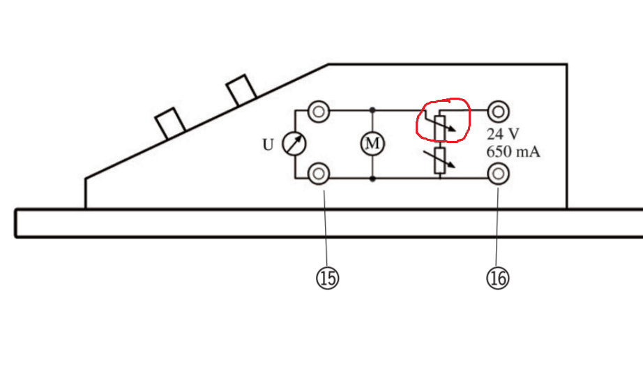
I have circled the symbol in question (red). It looks like a variable resistor, but the rest of the circuit is attached to the tail of the arrow. I feel as though this circuit is trying to describe a voltage divider. Is this true?
2 Answers
It looks like a variable resistor, ...
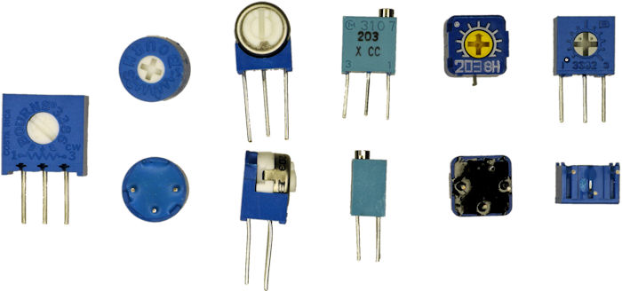
Agreed. The convention is that when the wiper arrow lies across the resistor that it is a preset potentiometer or"trim-pot" used to adjust or calibrate the equipment. These usually feature a screwdriver adjustment rather than a knob. (The regular potentiometer symbol arrowhead usually just touches the resistor at the midpoint.)
The lower variable resistor seems to set a minimum resistance value for the combination.
Figure 1. A selection of preset potentiometers. Source:Robot Room.
... but the rest of the circuit is attached to the tail of the arrow. I feel as though this circuit is trying to describe a voltage divider. Is this true?
That sounds right. It's difficult to know without knowing what the circuit is for and what U and M are.
Update after additional information was supplied:
U is a voltagemeter and M is a motor. On the device there are two buttons [knobs] that are used to adjust the voltage going through the motor. I figured that this would be done with the two variable resistors. Maybe this will be of some help? http://shop.skolebutik.dk/images/U15040_EN.pdf.
From the additional information supplied it appears that the incorrect symbol has been used in the diagram. They are regular potentiometers with knobs. I would expect the upper potentiometer's resistance to be 10× that of the lower one as the lower one is the fine adjustment.
It is a little unusual these days to control a motor's speed just with a potentiometer. A variable voltage regulator would maintain the motor's voltage much better than the simple potentiometer arrangement.
If they are both potentiometers, wouldn't the bottom one have no influence when varied?

simulate this circuit – Schematic created using CircuitLab
Figure 2. The circuit redrawn in conventional manner flowing from left to right and top to bottom. Note the connection of R2's wiper to one end of the track to create a rheostat rather than a potentiometer.
I think that it behaves as a non-variable resistor in that sense.
Correct. See the corrected diagram in Figure 2.
Would I be allowed to put an ammeter directly after the power supply and use the current read as the current in the motor in calculations? I know the resistors would also draw current, but I am wondering if this is negligible.
It would but, as you correctly think, you'd be measuring the potentiometer current too and since these must be low-resistance to provide enough current for the motor I think it would be no use. I would open up the box and add the ammeter as shown in Figure 2.
You say I am correct in stating that the bottom potentiometer behaves as a non-variable resistor, but later state that it behaves as a rheometer (which IS a variable resistor).
There are two ways to interpret the symbol.
- The wiper isn't connected to anything so it's just a resistor.
- It's a variable resistor.
Since they've used the same symbol for both pots they should have connected the wiper as I did in Figure 2.
On reconsideration I would state that the bottom potentiometer functions as a VARIABLE resistor used for fine tuning.
Correct. Their drawing could have been better. My Figure 2 should be less confusing.
-
\$\begingroup\$ U is a voltagemeter and M is a motor. On the device there are two buttons that are used to adjust the voltage going through the motor. I figured that this would be done with the two variable resistors. Maybe this will be of some help? shop.skolebutik.dk/images/U15040_EN.pdf \$\endgroup\$ Commented Feb 8, 2020 at 8:48
-
-
\$\begingroup\$ I am beyond confused at the moment. You say I am correct in stating that the bottom potentiometer behaves as a non-variable resistor, but later state that it behaves as a rheometer (which IS a variable resistor). On reconsideration I would state that the bottom potentiometer functions as a VARIABLE resistor used for fine tuning. Thanks for all the help though, I appreaciate it lots! \$\endgroup\$ Commented Feb 8, 2020 at 10:10
-
\$\begingroup\$ No problem. See the next update. \$\endgroup\$ Commented Feb 8, 2020 at 10:43
-
\$\begingroup\$ You've been such a blessing. Thanks again =). \$\endgroup\$ Commented Feb 8, 2020 at 11:30
The red circled component is a potentiometer. The one below it is a variable resistor. And yes, the two together form a voltage divider.


