0
\$\begingroup\$

I am using a CTHSCIC06 capacitive touch button and have connected as per the datasheet CTHSCIC06 capacitive touch button Datasheet application Circuit (the motor side of the circuit is not needed) however I am still having trouble around the pnp side of the circuit. I am using the BC557C. The circuit is set up in the following configuration:
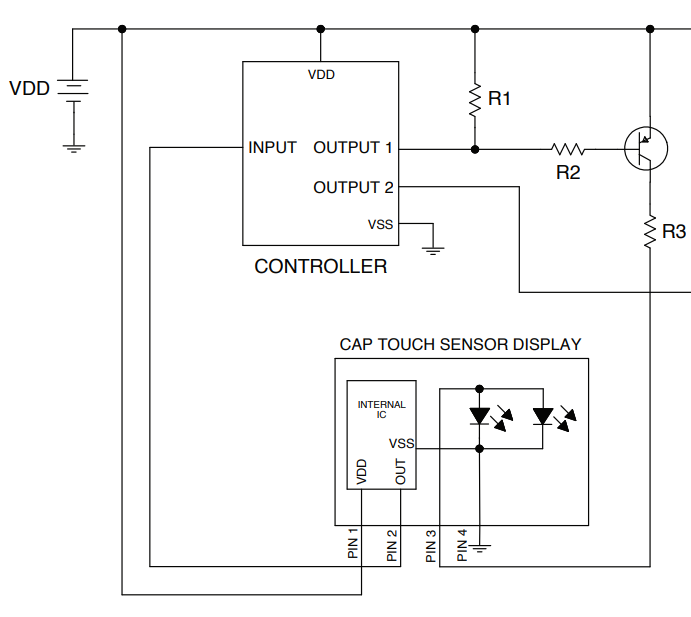
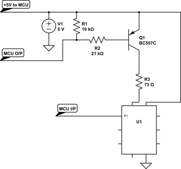
schematic

simulate this circuit – Schematic created using CircuitLab

The idea with the button is that when the button is pushed the LED will turn on and will give a +5V logic signal to the MCU. When the button is not pushed the led is off and the logic signal is 0V.

I have this soldered onto prototype board and it works fine when the power supply is from the USB connection from the PC to the ardunio however when I connect a power supply with +5V even when the the pnp is suppose to be off, there is still a low to medium glow from the LED within the capacitive push button as if it is on. But from probing the MCU I/P when the low medium glow is present it is 0V going to the MCU. So it seems when the LED should be off, it is still on but not on fully.

Originally I thought maybe voltage ripple but the ripple on the power supply is no more that 15mV. I also thought maybe the pull up resistor isn't pulling the line high but this works when powered from from the PC usb.

If you guys have any suggestions or advice that would be great.

Cheers UPDATE

So I checked the voltage of the MCU O/P pin and found when powered from the USB V=4.8V but when powered from external power supply V=4.1V. Could this be a reason why the line is not going fully high?

\$\endgroup\$
6
  • 1
    \$\begingroup\$ Lookintg at that schematic and ... What button? What LED? What is U1? \$\endgroup\$
    – user16324
    Commented Mar 25, 2020 at 19:57
  • \$\begingroup\$ @BrianDrummond U1 is the CTHSCIC06 capacitive touch button which has 2 LEDs built in, I have added the recommended config above \$\endgroup\$
    – Newbie
    Commented Mar 25, 2020 at 20:07
  • \$\begingroup\$ Your schematic doesn't show a connection between the 5 V GND and the MCU GND. Is there one? Do you really have two 5 V power sources as well as the MCU's? \$\endgroup\$
    – Transistor
    Commented Mar 25, 2020 at 20:13
  • 1
    \$\begingroup\$ You need to probe the MCU output voltage in both on and off states. \$\endgroup\$
    – user16324
    Commented Mar 25, 2020 at 20:13
  • \$\begingroup\$ what is "controller" \$\endgroup\$ Commented Mar 25, 2020 at 23:59

1 Answer 1

1
\$\begingroup\$

I would suggest you try placing the R1 immediately next to the base of Q1 so that it is between its base and emitter. That way it keeps the Q1 turned off if there is a small current going through R2. I would also suggest that you increase the value of R3 to anywhere from 220Ω to 680Ω (depending on LED's forward voltage and the total voltage applied, which I believe is around 2V and 5V respectively, as well as on the type of LED - is it superbright?); you could also reduce R2 to 10kΩ so that the transistor is more likely to work as a switch and not in its linear region.

\$\endgroup\$
1
  • \$\begingroup\$ thanks for that. The reason why R3 is 73Ω is due to in the device there is 2 LEDs in parallel each with a forward current of 30ma per LED, with a forward voltage of 3.2V so roughly R3 should be around 56Ω. If it was 220Ω I think that could be a little too dime. But I will definitely replace R2 to 10K. On the prototype board I do have R1 right next to the base. \$\endgroup\$
    – Newbie
    Commented Mar 25, 2020 at 21:17

Your Answer

By clicking “Post Your Answer”, you agree to our terms of service and acknowledge you have read our privacy policy.

Not the answer you're looking for? Browse other questions tagged or ask your own question.