0
\$\begingroup\$

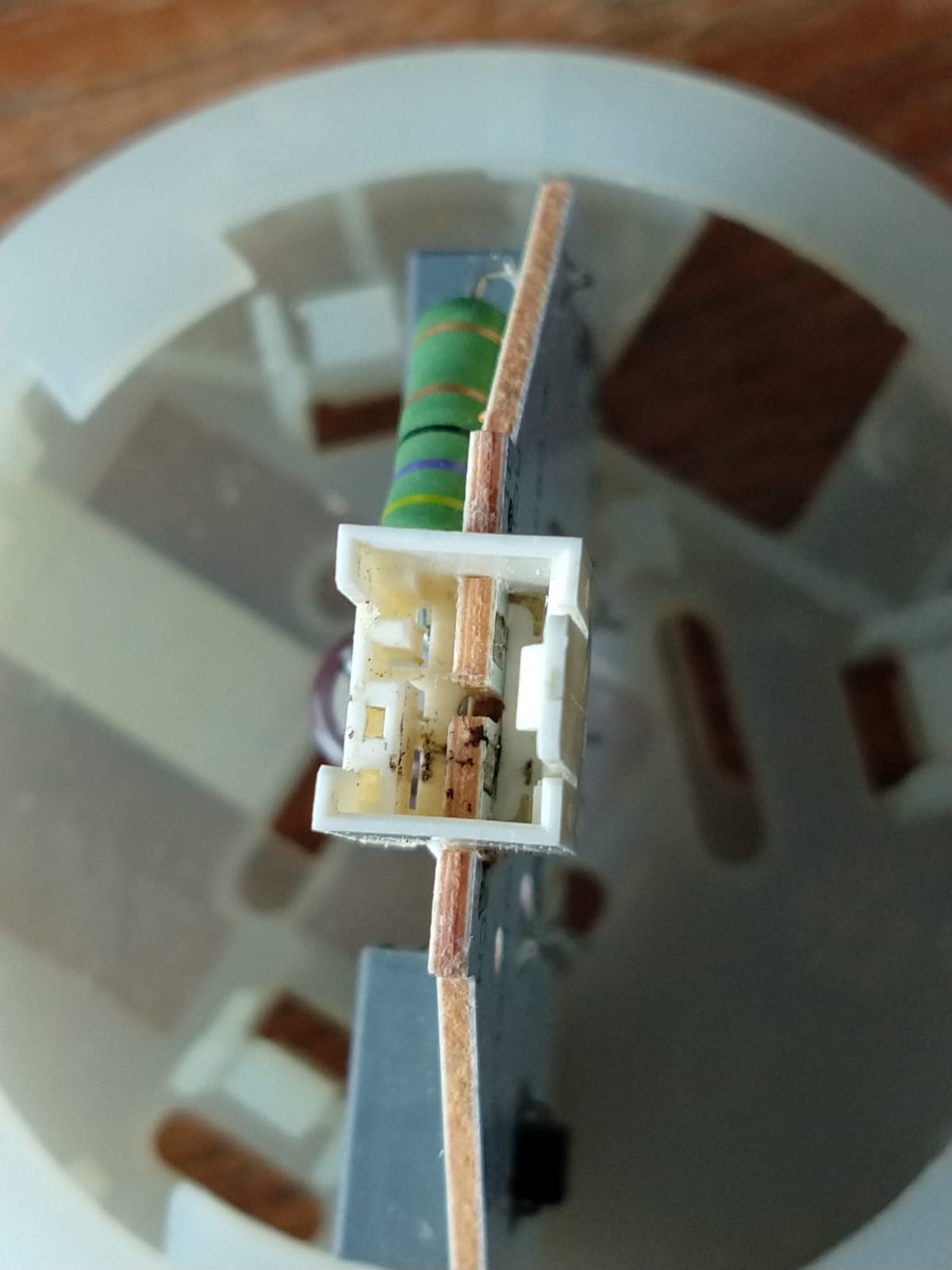
Recently, a rubber ring around the LED light inside my dishwasher broke, causing water to leak through. When it was replaced, I kept the old LED and I want to install it inside a closet, but I don't know the power connector to it.

Can anyone tell me what this connector is called and possibly what male cable I would need to connect to it?

There seems to be a place for 4 pins, but I don't know if it's in any way related to Molex.

Thanks in advance!

Photo of connector

EDIT

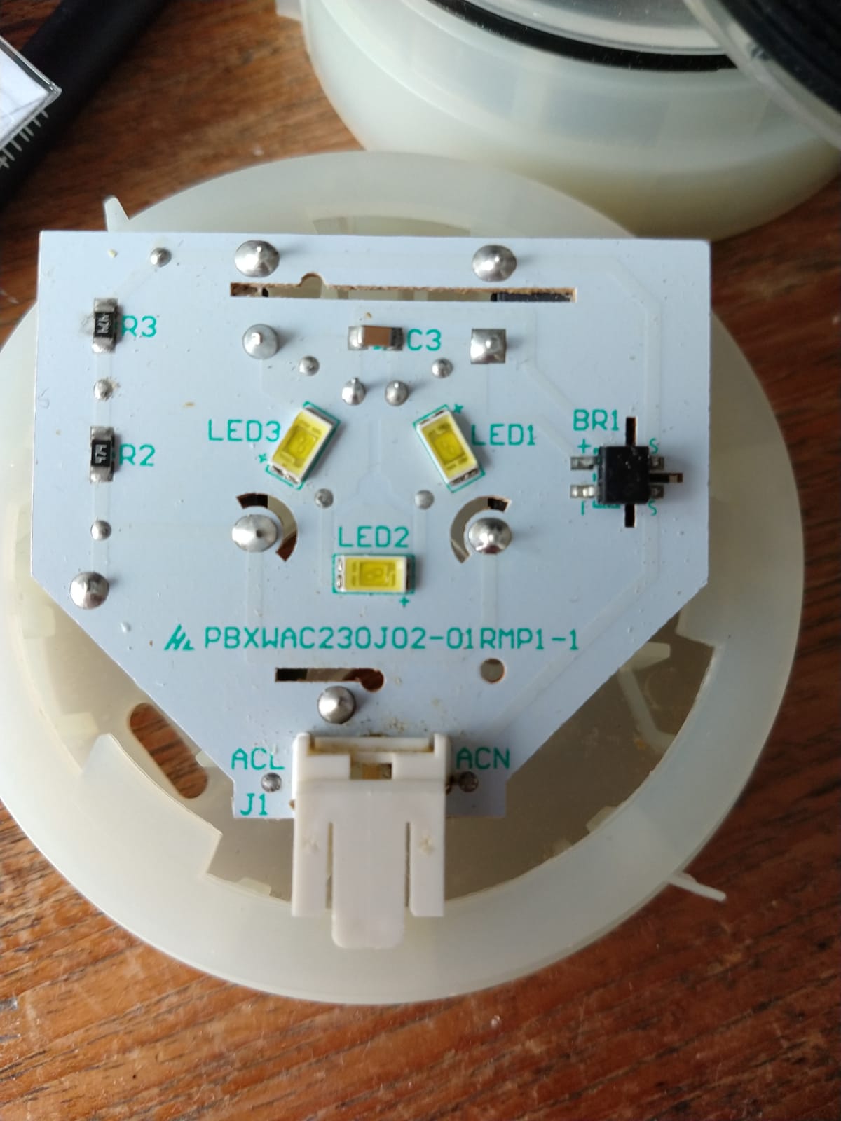
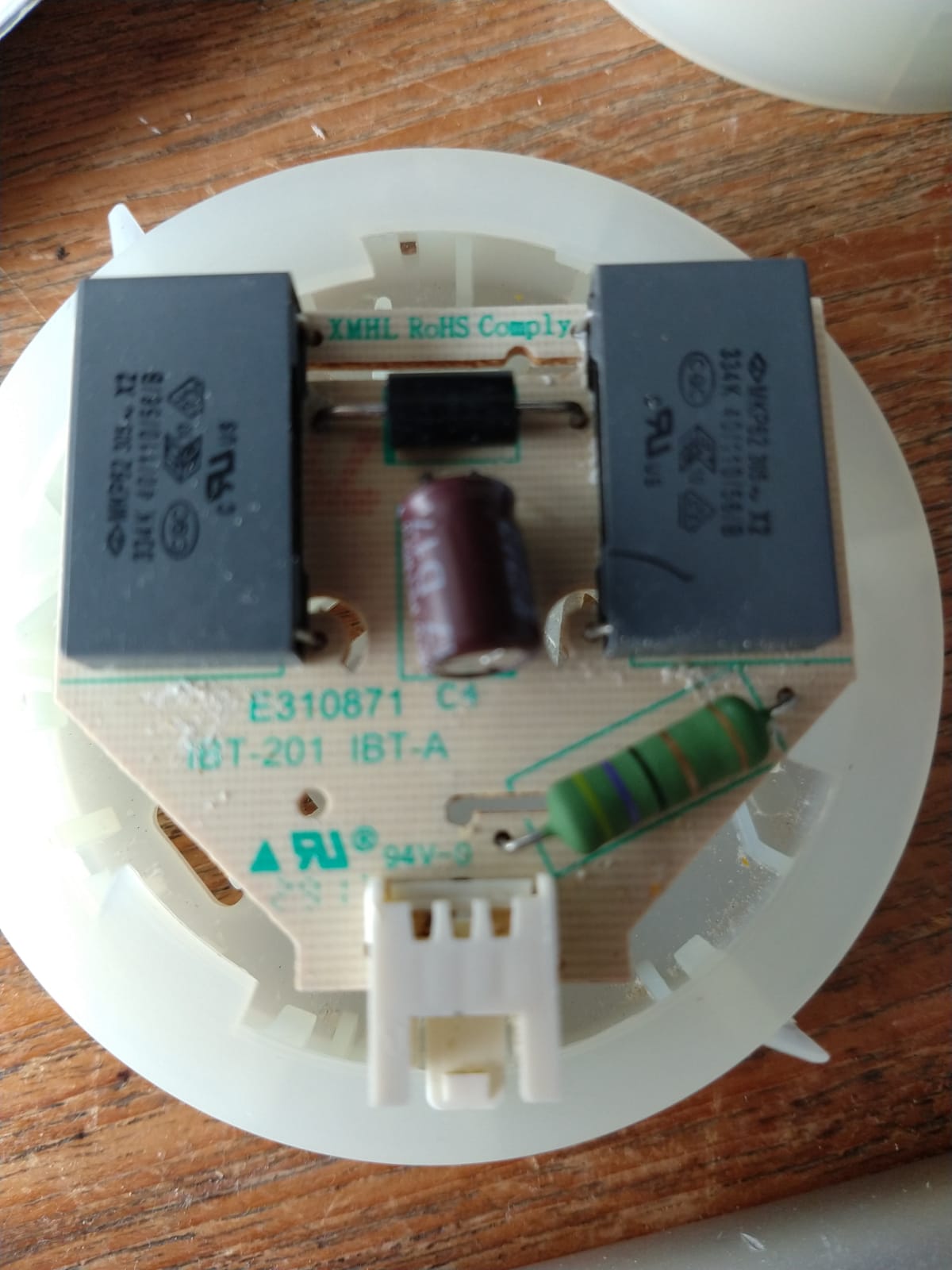
Two images of the top and bottom of the PCB

Photo of the top

Photo of the bottom

\$\endgroup\$
5
  • 1
    \$\begingroup\$ The simplest solution would be to solder wires on it, but you will need to reverse-engineer the circuit to know what kind of power it requires. I see a big resistor, so it's probably voltage driven, but what supply voltage does it need? \$\endgroup\$
    – bobflux
    Commented Apr 18, 2020 at 11:57
  • \$\begingroup\$ The body of the connect looks like a JST brand connector, however I do not recognise the specific connector used here \$\endgroup\$
    – Reroute
    Commented Apr 18, 2020 at 12:00
  • \$\begingroup\$ @peufeu I don't know. the resistor has colors yellow-purple-black-golf-gold, which would be a 47Ω resistor if I read it correctly? Isn't that very low? There is a 220µF 35V capacitor on there as well, so it might be 35V then \$\endgroup\$ Commented Apr 18, 2020 at 12:09
  • 1
    \$\begingroup\$ Maybe 24V? If you count the number of LEDs in series, at 3-3.3V each that will give you an idea of the voltage... Can you add a photo of the PCB? \$\endgroup\$
    – bobflux
    Commented Apr 18, 2020 at 13:27
  • \$\begingroup\$ I added a photo. Since there are 3 LEDs it would be 9-10V, right? Thanks a lot! \$\endgroup\$ Commented Apr 19, 2020 at 9:11

1 Answer 1

2
\$\begingroup\$

There seems to be a place for 4 pins

I understand what you mean, there are 4 spaces on the left side, but that's not how I see it working.

It looks like the PCB you have (containing the LED) has its contacts on the PCB itself - no separate connector pins there at all. I have marked the contacts on the PCB with red rings on this cropped edit of your original photo (there might be additional contacts on the hidden side of the PCB too). You can even see "scrape marks" where the contacts from the matching connector have slid along those PCB pads:
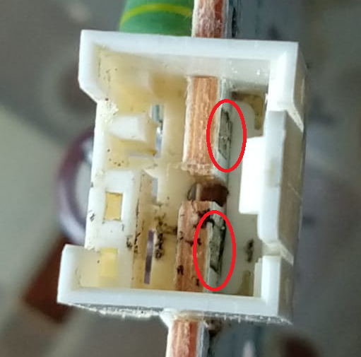
Crop of original photo, showing contacts

The white plastic part does not seem to contain any metal contact pieces itself, which again points towards the contacts being the PCB pads themselves. Based on that photo, I suspect the plastic part is just a latch, to hold the cable-mounted part (which is still inside your dishwasher) which has "PCB edge connector" contacts.

If I wanted to use that PCB, I would investigate removing the plastic part, as it only serves any purpose if you can get a matching part. After removing it, as peufeu commented, solder directly to the PCB contacts I have marked (or other equivalent places on the PCB, if you prefer e.g. equivalent component legs or vias etc. which are the same circuit nodes as those two pads). Secure the wires with hot glue etc.

Comments have mentioned how to drive the LED. You said:

There is a 220µF 35V capacitor on there as well, so it might be 35V then

No! If there is a 35 V capacitor on the PCB, across those PCB contacts, then the correct voltage to apply will not be 35 V (that would be an absolute maximum voltage).

It would need further investigation about the exact LED, which is not covered in your question about the connector, to learn how to drive it correctly (e.g. is it just one LED or multiple). Again, as peufeu commented, that investigation would need photos of the PCB to help reverse-engineer the schematic, and perhaps require you to do some tests (e.g. with a multimeter) to determine LED polarity (if that isn't obvious from how the capacitor is connected - the 220 uF capacitor will be polarised, so that may help).

If you still have access to the inside of the dishwasher, then some voltage measurements on the wiring to the replacement LED board might also be helpful.

\$\endgroup\$
1
  • \$\begingroup\$ Thanks a lot! I can't believe I didn't see those. Removing the plastic casing was easy, and there were no other metal parts hidden behind it. Since the top of the PCB has ACL/ACN printed on it, that should tell me the direction of the current, but as you've probably guessed, this is my first electronics project. \$\endgroup\$ Commented Apr 19, 2020 at 9:17

Your Answer

By clicking “Post Your Answer”, you agree to our terms of service and acknowledge you have read our privacy policy.

Not the answer you're looking for? Browse other questions tagged or ask your own question.