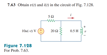
In the circuit of the above problem, at time t = 0-, the inductor can be modeled as a short circuit as the circuit is at steady state. The 20 ohm resistor can be ignored since all current flows through the short circuit. I think this means that the voltage through the inductor at t = 0- is 0 V, since it is part of the ground node. It seems that at t = 0+ the inductor voltage should also be 0 V, as the source voltage is 0 V, but this is not correct. At time t, the correct value of inductor voltage for t ≥ 0 is -8e^(-8t) u(t) V, where u(t) is the Heaviside function. From this expression, the inductor voltage t = 0- is 0 V, while at t = 0+ it is -8 V. How can these values of inductor voltage be interpreted?
-
1\$\begingroup\$ What do you mean how can it be interpreted? -8 V is 8 V less than 0 V. There's nothing special about it. Remember that the current through the inductor is a continuous function. So if -8 V is needed to keep pulling current from the voltage source after its output voltage switches to 0 V, that's what the inductor will produce. \$\endgroup\$– The PhotonCommented Apr 20, 2020 at 2:52
1 Answer
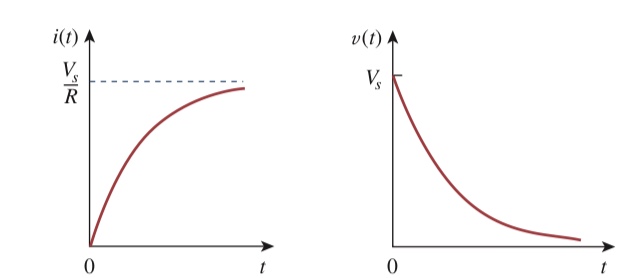
The circuit you’ve shown is an RL circuit with a step voltage input thus it would give a step response. This step response would be a inductor current that is of the form of a rising exponential like shown below. It’s inductor voltage would be a decaying exponential. The current rises because as we approach steady state the inductor acts like a short. The voltage is at peak initially because the magnet field in the inductor produces a voltage instantly, then voltage decays.

Source: Fundamentals of electric circuits 5th ed Alexander/Sadiku
I believe when you derived the inductor current you took the derivative incorrectly and got a negative value. Only in a source free RL circuit would we get a negative voltage across inductor because of the rapid collapse of magnetic field producing a voltage as to try to maintain current through inductor.

