5
\$\begingroup\$

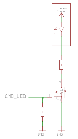
Let's consider the following simple example :

enter image description here

An MCU controls the lighting of an LED with the wire "CMD_LED" by switching the state of an NMOS transistor.

When CMD_LED = 1, the transistor is closed and the LED is lighted.

When CMD_LED = 0, the transistor is opened an the LED is off.

The red rectangle can be connected or unconnected from the circuit.

I want to detect an unconnected LED. To do so I have to use an ADC input of the MCU to measure a specific voltage. I cannot measure the voltage inside the red rectangle.

Is it possible to detect that the LED is unconnected, based on this method ? If so where should I measure the voltage ? I don't know how the MCU can distinguish between the unconnected LED and the open transistor...

Thanks for you help. :)

\$\endgroup\$
4
  • \$\begingroup\$ What is the voltage at Vcc+? \$\endgroup\$
    – Transistor
    Commented Apr 28, 2020 at 15:11
  • \$\begingroup\$ If you measure between the resistor and the LED you'll see : VCC (transistor OFF or LED failed short circuit), VCC - 2 or 3V (LED on) or 0V (LED open circuit with transistor ON) \$\endgroup\$
    – user16324
    Commented Apr 28, 2020 at 15:42
  • \$\begingroup\$ You'd think that, but the LED leakage will take the drain all the way up to Vcc in a couple of ms. Try the sim in my answer. \$\endgroup\$ Commented Apr 28, 2020 at 16:05
  • \$\begingroup\$ Measure the voltage across a resistor in series with the LED. \$\endgroup\$
    – Hot Licks
    Commented Apr 29, 2020 at 0:28

2 Answers 2

8
\$\begingroup\$

A long time ago for a product, I worked out this issue by using a current mirror. Basically, I used a matched NPN pair wired up as a mirror and sent a very small (tens of microamps) current to the LED, not enough to light it. The mirror output swung enough voltage that it could read it with a GPIO. Once my diags were done I turned off the current mirror so even the phantom sense wasn’t present. Why did I go to so much trouble? I was very short on GPIOs and needed to resort to some tricks to reuse them.

The ADC can measure the FET drain voltage with the FET ‘off’, with a bit of work. First, toggle the FET 'on' then 'off' to discharge the drain and trace capacitance, then quickly sense the drain voltage afterward. The voltage will stay at 0 if the LED is unconnected, or drift up towards Vcc with the LED present as the LED leakage bleeds off charge.

That said, the ADC sensing method poses a couple of difficulties: ADC input range (which needs to include Vcc), and ADC input impedance loading the circuit when the driver FET is 'off'. Either one will prevent proper sensing of the FET drain charge.

What to do then? Forget the ADC. There's an easier way.

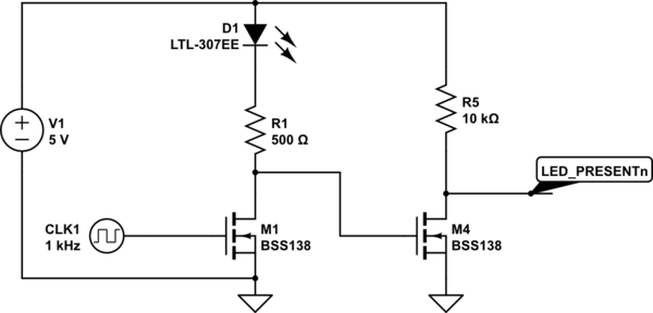
Use an nFET to watch the driver drain voltage. Just like with the ADC method: pulse the driver 'on' then check the FET state shortly afterward. If the sense FET stays off, no LED; if it turns on, LED is connected. Try it, here:
schematic

simulate this circuit – Schematic created using CircuitLab

This circuit takes advantage of the fact that there's a bit of capacitance present on the driver FET drain and the board trace. The sensing nFET doesn't load this, and so can detect the driver drain off-state charge with the LED present or absent.

\$\endgroup\$
3
\$\begingroup\$

Measure the voltage at the point where the resistor connects to the LED. If you set CMD_LED high then the voltage at this point will rise significantly if an LED is connected. If an LED is not connected then the voltage will stay near zero.

You can test for the presence of the LED without lighting it long enough for a human observer to notice. I think if you asserted CMD_LED for less than a millisecond you would still see a large voltage change at the top end of the resistor.

\$\endgroup\$

Your Answer

By clicking “Post Your Answer”, you agree to our terms of service and acknowledge you have read our privacy policy.

Not the answer you're looking for? Browse other questions tagged or ask your own question.