2
\$\begingroup\$

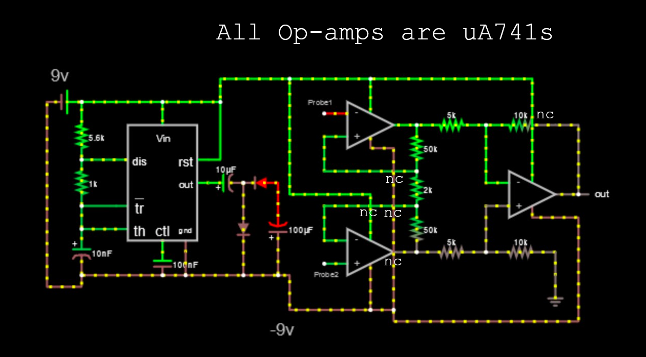
I am a visual art student and I'm currently developing a project which involves recording bioelectrical activity in plants. I am totally new to this game so I’m just wondering if anyone can have a look at this circuit to see if it might work.

The NC on the image means not connected. I've never drawn up a circuit before so I had to run wire over other wires. The circuit diagram just shows where connections are.

I used falstad to make it http://www.falstad.com/circuit/ The left hand side of the circuit gives a negative voltage for the Op amps to work. The right hand side of the circuit with 3 op amps is the instrumentation amp which is supposed to take the small signal of the plant and subtract all the noise I don't want and then amplify it for an arduino to read.

I'm also wondering if anyone has any advice on what sensors to use. enter image description here

Please let me know your thoughts.

\$\endgroup\$
10
  • 3
    \$\begingroup\$ It's probably cheaper, easier, and cleaner to just use two 9 volt batteries to power the amplifier than to generate a negative voltage using a 555. \$\endgroup\$
    – JRE
    Commented May 25, 2020 at 11:19
  • \$\begingroup\$ scholar.google.ca/… \$\endgroup\$
    – D.A.S.
    Commented May 25, 2020 at 11:47
  • 2
    \$\begingroup\$ Choose a single-supply INstrument Amp IC's (INA) analog.com/media/en/technical-documentation/data-sheets/… with STP cable. Even better shop/buy the cards with this or similar IC, \$\endgroup\$
    – D.A.S.
    Commented May 25, 2020 at 11:59
  • \$\begingroup\$ Use File Export ( copy ) then insert link here in future. What kind of signal monitor would you like? like an EKG or EMG amplifier? Lots of those \$\endgroup\$
    – D.A.S.
    Commented May 25, 2020 at 12:25
  • 1
    \$\begingroup\$ @EdV: Yeah, and there was a cheesy science fiction short story that made a pun of it. Somebody found that plants were sensitive to murder and such things, and built a detector to find people torturing or otherwise doing terrible things to other people. Long plants worked better for direction finding, and grape vines can be grown very long. When asked how he found a killer (or other baddy) the guy explained about the plants and having to use a long plant for direction finding. The story ended with some play on "I heard it through the grapevine." Now I have to go and find that story again. \$\endgroup\$
    – JRE
    Commented May 25, 2020 at 15:22

4 Answers 4

3
\$\begingroup\$

Here are a few problems you are going to run into:

  1. Your circuit will output a voltage that ranges between +7 volts and -7 volts. The Arduino analog input can accept voltages between 0 volts and +5 volts.
  2. The charge pump you built around the 555 will be electrically "noisy." It will produces interference in the signal you are trying to measure, making your task much more difficult.
  3. The 741 is not known for high performance. It was a wonderful part back in 1963 when it was developed, but it has been surpassed by just about everything produced in the mean time. It will cause you all kinds of difficulties in measuring very weak signals.
  4. The input impedance of your proposed circuit is likely far too low. This paper mentions measuring millivolt level signals using a commercially available voltmeter with an input impedance in the gigaohm range. Your circuit will probably have an input impedance of several hundred kiloohms.

You need to do a few things before you get started:

  1. Determine just what a biolectrical signal looks like.
    • Is it DC?
    • If so, how do you determine the polarity?
    • If it is AC, what frequency range can you expect?
    • Regardless whether it is AC or DC, what voltage range can you expect?

That all determines what you are going to have to do to get a signal that the analog to digital converter of the Arduino can work with. That's gain (amplification) and level shifting (will you have to move negative voltages up above zero) and bandwidth of the amplifier.

  1. Given the very weak signals, it might be better to use a second battery instead of a charge pump to generate a negative voltage source.
  2. You need an instrumentation amplifier with high impedance inputs. You won't be getting that from an in-amp assembled from the 741. Use a proper in-amp and save yourself a lot of hassle.

There are a lot more details you'll have to handle. The points I listed are just a starting point. You've picked a difficult task, and don't have enough details to really plan things yet. You are going to have to gather details and knowledge about the subject. As you progress, I expect you'll find things you didn't know you needed to consider. Come back and ask specific questions about those things.

\$\endgroup\$
2
\$\begingroup\$

Ah, that takes me back. I was thirteen in the summer 1971, listening to the constant the squealing whine of my audio oscillator responding to changing resistance on the germanium leaf, detected by a diff amp uA741 "amplifier chip". (I mean, GERANIUM leaf. Heh.) I used a couple of silver quarters as electrodes, wetted with tap water.

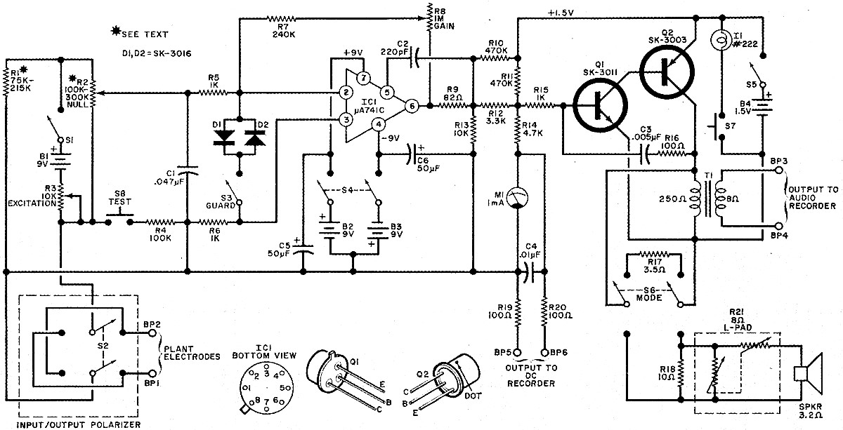
I got it all from this classic DIY project article:

MORE EXPERIMENTS IN ELECTROCULTURE, June 1971, Popular Electronics
enter image description here

The LM741 op amp is still being sold, but try this less-obsolete version: TL071CP jfet-type (or for the quad version try TL074.) The TL071CP has the same pins as the 741, but much higher input resistance.

For modern electrodes I'd try ebay search: disposable agcl electrodes: https://www.ebay.com/sch/i.html?_from=R40&_nkw=agcl+electrodes&_sop=15

You'll need a third gnd/ref electrode buried in the damp plant soil, connected to the supply common.

For the original stories about plant emotions, look up Cleve Baxter, and note that he used a lie-detector (polygraph) GSR instrument, NOT the eeg/ekg instrument in your Falstad schematic. (GSR is an ohmmeter which measures skin resistance. It applies a low voltage to electrodes, usually via a Wheatstone Bridge circuit.)

https://en.wikipedia.org/wiki/Cleve_Backster

Notice that the 1971 schematic above does use an adjustable Wheatstone bridge, with the plant being in one of the legs, and where one of the plant electrodes is circuit gnd/common. The R2 pot provides the other two legs of the bridge, while R1 is chosen to roughly equal the ohms of the plant (so that the R2 pot can be set near the center of its sweep.)

One thing I wanted to try: add more channels! Build three of these (or more,) with an electrode on each plant leaf. Then play all the little audio-beepers at the same time, for a quavering chorus. Will they all respond, if you torture some bacteria, eat an apple, fry an egg? Another idea: use the "squealing wall" laser interference demonstration w/photodiode and mirror, but aimed at a growing plant tip. The growth should produce an audio signal, ten micron/sec growth gives 25Hz. Massage the photodiode signal to produce clicks, one click per 300nM growth.

Besides C. Baxter, also Chandra Bose in 1902 was doing something similar, but using "optical levers" in the form of tiny mirrors deflected by growing plant tips, to record a trace on photo film. He wanted to test the effects of various fertilizers on growth-rate, but instead discovered the "plant emotions" effect. Also he claimed that plants could be knocked unconscious by anesthetic gas (halting growth until they "woke up.")

Another story is this one:

Electrically-shielded potato

A piece of potato was sealed in a thick metal chamber and monitored by an oxygen sensor. Apparently the potato didn't like certain people. Also, it apparently responded to human presence (when the lab was empty during weekends.)

The "plant cresograph" invented by JC Bose in late 1890s enter image description here

\$\endgroup\$
1
\$\begingroup\$

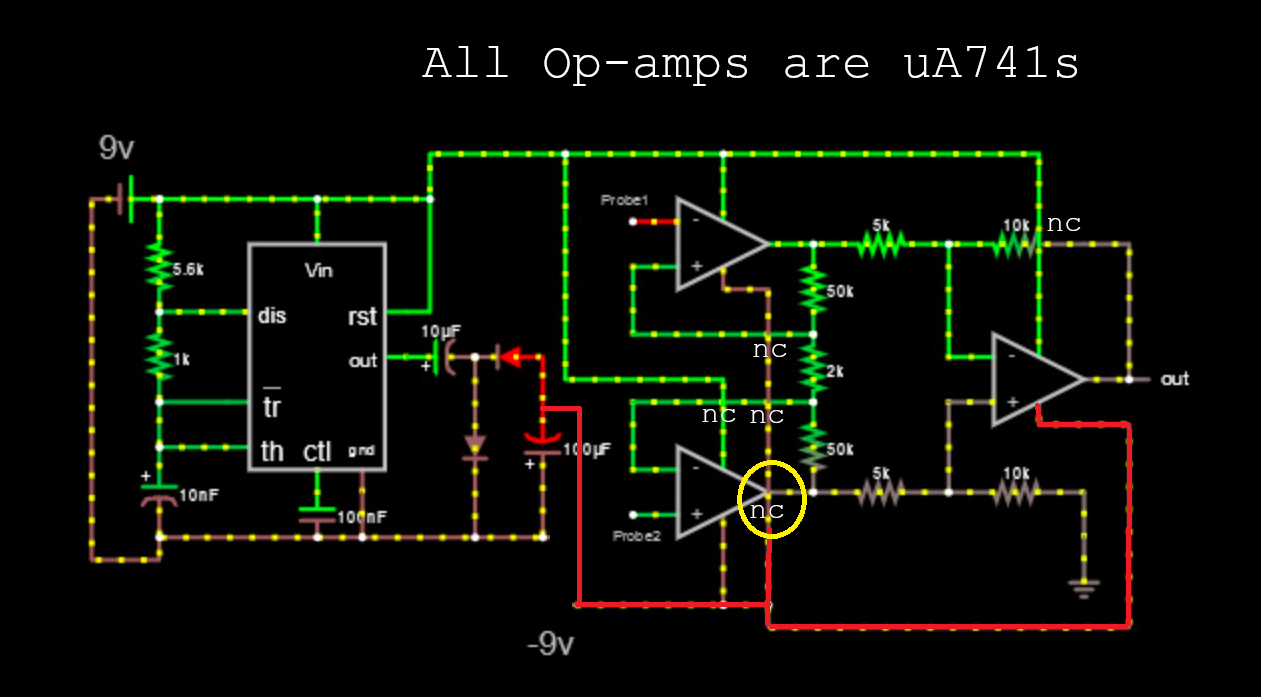
A couple of errors (apart from using the dinosaur 1963 pre-death of JFK 741 op-amp): -

enter image description here

  • You didn't properly attach the -9 volt source to the op-amp negative rail pins. See my modification in red.
  • I think you have a short where I've drawn the yellow circle

Did I say that Falstad is very ugly. Micro-cap 12 is much superior, comes with all the libraries bundled-in and is now totally free. Pro-gear in my opinion.

The sensor connections are also very important - I can't say whether your circuit will work because I only eat plants and don't worry about their biometrics during the consumption phase but, without a recognized impedance on the two inputs back to ground I can assure you that it won't work. Try using a real InAmp design and not one using the 741. There are chips available that will do this.

\$\endgroup\$
9
  • \$\begingroup\$ Andy is not familiar with Falstad or why is short comment is in error. \$\endgroup\$
    – D.A.S.
    Commented May 25, 2020 at 12:03
  • 2
    \$\begingroup\$ @TonyStewartSunnyskyguyEE75 if the pre-school-level falstad showed numbers for voltages on nodes (like sensible simulators that I could mention) instead of stripy coloured wires then there wouldn't be an argument here would there. It's a toy. \$\endgroup\$
    – Andy aka
    Commented May 25, 2020 at 12:07
  • \$\begingroup\$ The toy is in the skill of the user. \$\endgroup\$
    – D.A.S.
    Commented May 25, 2020 at 12:08
  • \$\begingroup\$ Hmm that is yet to be demonstrated then LOL \$\endgroup\$
    – Andy aka
    Commented May 25, 2020 at 12:11
  • \$\begingroup\$ THis S-D ADC took me 2 minutes with floating scope traces tinyurl.com/y8qaykr4 \$\endgroup\$
    – D.A.S.
    Commented May 25, 2020 at 12:14
0
\$\begingroup\$

There are many* research articles on microbiology with electrical measurements much like 1~100 uV EEG for humans. The impulses occupy a low frequency band and range from 0.1 Hz to 40 Hz rep rates with risetimes occupying 20x this in bandwidth. (where T rise=0.35/f -3dB)

A better solution to both applications is the low cost INstrument Amp (INA) from TI. https://www.ti.com/product/INA114 . Earth Grounding essential to reduce stray AM radio and power line stray signals. Shielded twisted pair (STP) cable is recommended. It has the high impedance desired with low input bias current and like the 3 Op Amp config you have drawn except much lower input bias current. (BTW your probe 1 inputs are reversed)

What you have shown is an Astable pulse circuit and 3 Op Amp version of an INA for measure some impedance at some pulse rate. This might not be as interesting as actual chemical impulses generated by the plant.

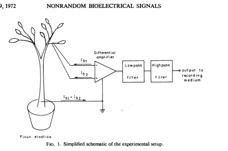
Shield ground provides a sink to RF noise in the moist soil so that differential measurements can be made from point A to B. enter image description here The LPF and HPF can be combined in the INA with suitable caps.and resistors for chosen T.rise times.

Consult with biology researchers for electrodes or read old report in my link. ( I did not)

p.s. When using Falstad's rubber band mode on the ends of wires using CTRL+mouse to move end point and Options > show Current (disable). Also simply use basic Op Amps and add 220 Ohms to output if you want. The simulations work faster. Then Use "V" to add a voltage source and "g" to add a ground instead of long lines. but dont add two 2 gnds or 2 V+'s together.

\$\endgroup\$
1

Your Answer

By clicking “Post Your Answer”, you agree to our terms of service and acknowledge you have read our privacy policy.

Not the answer you're looking for? Browse other questions tagged or ask your own question.