1
\$\begingroup\$

Need some help making these IR Emitter/Receiver circuits, and their power, more stable.

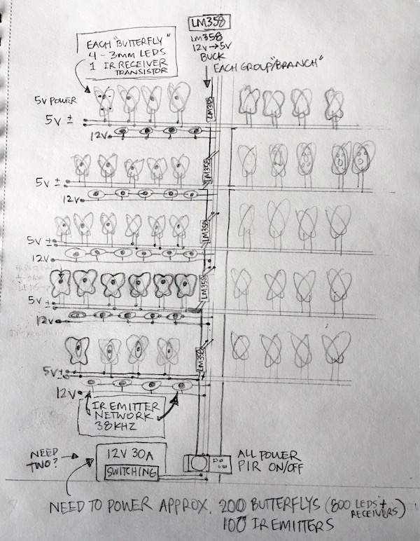
Building a large, 8’ x 10’ LED art installation (in progress details included). LED Butterflies in a grove of trees that interact with the viewer. Built in to the installations “tree” structure will be a field of IR Emitter signals with individual IR Receivers (built as “Butterflys”) triggering a group of LEDs on/off as viewer walks into and out of the area.

The conception is a large array of IR emitter signals - emitting at 38Khz for a distance of approx one meter - and a similar large number of “Butterflys”, each with its own receiver-transistor-LED load turned on by the reception of a signal bouncing off a viewer nearby (otherwise off).

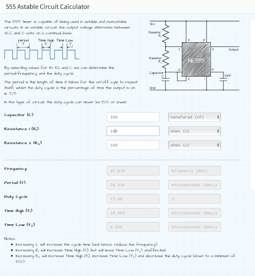
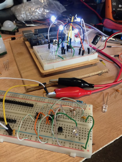
Works in the test circuit but it does so only for a moment. The amps fluctuate from the emitter’s bench power source, starting at 20 mA increasing to 40 and higher. Once the amperage goes hi from the emitter, the LEDs on the receiver turn off. That’s bad. They need to stay on for as long as a signal is being received. Not sure how to stabilize that 38Khz signal from the emitter LED. Circuits are the simple and common ones found everywhere and the astable 555 timer/ IR Emitter values are derived from an online calculator. I understand that the wiring in the test circuit is very messy and that contributes to the instability BUT should these circuits work as proposed if all components are neatly on a small PCB? The emitter PCB would be shaped like a "leaf" and the separate receivers PCB would be shaped like the butterfly's body. Would there be any suggested changes I should make/adjust with power and or resistance BEFORE I send the schematics to a PCB shop?

Probably should go without saying, but I’m an artist not an engineer. Need help keeping these circuits solid, simple, small and powered for the interaction/art to show through. Side note: I’ve been looking for EE consultation, am willing to pay reasonably for time/expertise, but since this isn’t a commercial application, I can’t find anyone willing (consult suggestions welcome:) Please help.

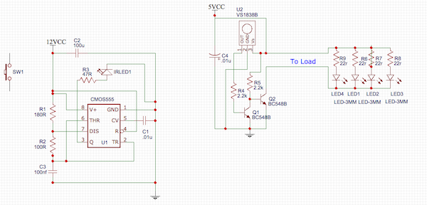
IR EMITTER - RECEIVER CIRCUITS

LED INSTALLATION CONCEPT

38Khz Timer Calculator

Messy wiring INSTALLATION DETAIL -IN PROGRESS

\$\endgroup\$
4
  • \$\begingroup\$ Check the voltage at 5Vcc when the LEDs go out. See that it stays 5V. Where is 5V coming from in your test circuit? \$\endgroup\$
    – JRE
    Commented Dec 4, 2018 at 21:47
  • \$\begingroup\$ For the test circuit, the power is coming from two sources - emitter from a bench supply and receiver from a 5v 30 amp switching power supply. When I test the RECEIVER separately, using a spare remote control, it works great. LEDs stay on for as long as the signal. Next test: the EMMITER voltage stays the same 5V throughout, as per the bench top supply. It's the amps that fluctuate. I assume that messes with the 38 Khz signal? \$\endgroup\$
    – adlib33e
    Commented Dec 4, 2018 at 21:59
  • \$\begingroup\$ I hope that the 12V on that 555 ir the LED resistor is a mistake. Otherwise you are pulling a lot of current through that IR LED and out of the 555. A rough estimate tells me you are dumping about 1.5W., that is a considerable amount of heat for a small LED. \$\endgroup\$ Commented Dec 5, 2018 at 4:37
  • \$\begingroup\$ It was, Edgar Brown. Everything was running on the same 5v bus. \$\endgroup\$
    – adlib33e
    Commented Dec 5, 2018 at 15:16

1 Answer 1

3
\$\begingroup\$

I see a fatal flaw with the infra-red optical link.
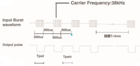
The infra-red receiver is expecting a "bursty" string of 38 kHz pulses. Data sheet explains that the 38 kHz should be on momentarily, about 600 microseconds, then off for 900 microseconds. The Chinese data sheet specifications are difficult to decipher:
ir receiver burst timing
When you transmit a continuous 38 kHz (as you are doing), the receiver becomes accustomed to the signal, just as your eyes become accustomed to the bright sun (and close down its iris). At least one user has noted that this receiver is also prone to sunlight-desensing. Other similar receivers might do better.

Your basic idea is sound, and that IR-receiver can work over the 1 M distance easily. Your 555 circuit driving the IRLED needs an additional timer to "break" for 900 microseconds.
The IR-receiver should include some way of keeping active low during that 900 microsecond break. I have added a 0.22uF capacitor to accomplish this function, but have made an assumption that the internal pull-up resistor is 39k ohms. Many IR-receivers have about this much resistance - the Chinese data sheet may not specify this part. The R1*C1 time constant is critical to bridge the needed 900 microsecond break:
improved LED driver to remove 900 us. burst I would use a very small microcontroller instead of 555 timer to drive the IRLED...fewer parts. It can generate the 38kHz burst lasting 600 microseconds, and time out the 900 microsecond "off" period too. It might even be able to drive the IRLED directly through a small value resistor.

;Drive an infra-red LED cathode with digital output pin GP2.
;LED anode goes to +5V thru small series resistor, at 38000 Hz.
;23 cycles of 38 kHz, lasting about 600 microseconds
;turn IRLED off (high), lasting about 900 microseconds.
;Repeat this sequence forever.
;Default internal clock speed is 4MHz: instruction rate is 1000000/sec.
;All timing depends on 1MHz instruction rate!
;DON'T FORGET TO PULL notMCLR to LOGIC HIGH, else nothing runs!! Don't let it float.
;If you pull notMCLR low, IRLED goes off, until notMCLR goes high again.
;Watchdog timer is active - code resets it.
;By default, internal comparator is disabled from interfering with GP2 output pin.
;December2018
;
#include p10f200.inc        ;register names defined here
;Macros:
#define ledon bcf GPIO,GP2  ;turn IRLED on by dragging cathode low.
#define ledoff bsf GPIO,GP2 ;turn IRLED off by dragging cathode high.

 __CONFIG _MCLRE_ON         ;GP3/MCLR pin functions as MCLR input..pull it high with
                            ;a resistor to light up LED. Pull it low to turn LED off.

cnt         equ 0x10        ;first available RAM location
burstcnt    equ 0x11        ;a counter for burst length
;---------------------------------------------------------------
;
    ORG 0000h           ;start address from power-up or watchdog
    andlw 0xFE          ;reset to zero least sig bit: disable FOSC/4 output on GP2
    movwf OSCCAL        ;write oscillator calibration byte.
    b   setup           ;go configure this simple environment...
;   
setup:
    movlw 0xDF          ;make GP2 available as programable I/O pin rather
    OPTION              ;than TMR0 clk...write it to OPTION register
mainloop:
    movlw 0x0b          ;make GPIO 2 an output (not input) for driving IRLED
    tris GPIO
    movlw .23           ; init counter for six-hundred microsecond loop timer
    movwf burstcnt      ;it will be decremented to zero later.

shloop:
    ledon               ;macro to turn on IRLED
    movlw 3             ;now waste some time....about 13us.
    movwf cnt
    decfsz cnt,f        ;a short time-wasting loop
    b $-1               ;loop for LED off period.
    clrwdt              ;clear the watchdog so it doesn't disturb us.

    ledoff              ;macro to turn off IRLED
    movlw 3             ;now waste some time....about 13us.
    movwf cnt
    decfsz cnt,f
    b $-1               ;time-wasting loop for LED on.
    decfsz burstcnt,f   ;done with 600 us burst?
    b shloop            ;no, complete this burst with more 38 kHz. cycles
;--------------------------------------------------------

    ledoff                  ;turn IRLED off for remaining 900 microseconds
    movlw   .149            ;time-wasting counter for 900 us.
    movwf cnt               ;initialize off period count
nhloop:
    nop
    nop
    nop
    decfsz cnt,f
    b nhloop                ;countdown loop for LED off period.

    b mainloop              ;start again....600:on, 900:off loop forever
;--------------------------------------------------------
    END                     ;finish assembler code.
\$\endgroup\$
11
  • \$\begingroup\$ Thanks for pointing that out. Wouldn't 600/900 be the duty cycle which could be adjusted with different capacitors/resistors, instead of a second timer? I actually would have loved to connect each butterfly/led group to a micro controller so that there would be both individual control (for animations, etc) as well as the on/off trigger But that circuit design is waaaaay out of my league, for both hardware (op amps, signal distance, power control, etc) and software (array management). Anyone willing to help with that? \$\endgroup\$
    – adlib33e
    Commented Dec 4, 2018 at 22:24
  • 1
    \$\begingroup\$ You need two oscillators or timers: one to generate the 38 KHz, and another to makes that come and go - TV remotes encode information in enabling/disabling the 38 KHz, so yours must also switch on and off or it will be rapidly ignored. A simple MCU may well be the best way to do this; you could also potential transmit unique codes to avoid mutual interference, at least if you do them at different times. \$\endgroup\$ Commented Dec 4, 2018 at 22:41
  • 1
    \$\begingroup\$ @adlib33e No, two 555's required - there is a dual 555 chip available. We generally discourage 555 circuits - microcontrollers are far more appropriate for this task. Have added edits to update your receiver circuit to bridge the 900 us gap. \$\endgroup\$
    – glen_geek
    Commented Dec 4, 2018 at 23:11
  • \$\begingroup\$ When talking about a small micro controller, are you speaking of something like this? 556-ATTINY412-SSNR - 8-bit Microcontrollers - MCU 105C, 5.5V, Green, 20MHz, SOIC8, T&R (from Mouser) Datasheet: mouser.com/datasheet/2/268/40001911A-1220759.pdf ...Also searching for the Arduino code to control the Signals 600 ns on, 900 off as we speak \$\endgroup\$
    – adlib33e
    Commented Dec 5, 2018 at 5:28
  • 1
    \$\begingroup\$ We're discouraged here from recommendations. Any microcontroller (including the most bare-bones) is appropriate, even ATtiny212, to replace 555 circuits. I'd look for one that could drive IRLED current directly from a logic output pin. Choose a code-development environment that you're comfortable with, along with easy-to-use flashing hardware - you're going to spend considerable time on the learning curve if you're new to microcontrollers...I'd consider this a straightforward starter project, after doing the blinky-LED project that everyone starts with. \$\endgroup\$
    – glen_geek
    Commented Dec 5, 2018 at 13:56

Your Answer

By clicking “Post Your Answer”, you agree to our terms of service and acknowledge you have read our privacy policy.

Not the answer you're looking for? Browse other questions tagged or ask your own question.