2
\$\begingroup\$

Task is to switch 2 loads with an MCU (3.3V 10mA max) and few IRF630N, BDW93C and sample pack of S901x transistors (of switch relevant components).

12V loads, likely important context for question:

  • 0.3A 3-pin fan, want speed control, research points to low frequency PWM method
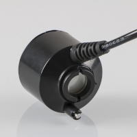
  • 2A XL6009 based boost converter with enable pin, which in turn feeds 24V ultrasonic mist driver (picture 3). Duty cycle around 20s/on 300s/off so I figured keeping converter always connected and switch 24V is not optimal, please point if wrong

According to my poor understanding of datasheet, IRF630 would barely open at 3.3V so additional transistor is needed to run it, so I tried darlington first and am very surprised at observed voltage. Open state: -1.1V closed: short burst to 18V, then steady 12V as wanted. Don't have oscilloscope yet, measured with cheap digital multimeter.

Question 1: please explain negative and burst voltage on load connector. Is it bad? If yes, how to fix it?

Question 2: please advice how to properly switch described loads with listed components.
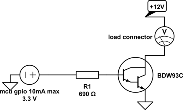
schematic

simulate this circuit – Schematic created using CircuitLab

Just in case I messed up wiring, here is real photo. Long "bus" wire on the right is common. BDWs' pin 1 soldered with limiting resistor to GPIO wire. BDWs' pin 2 go to their load (-). BDWs' pin 3 connected to common.

photo of real wiring

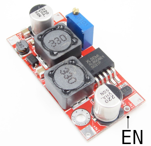
Photo of load2, XL6009 based DC-DC converter with enable pin and its load, ultrasonic fog device.

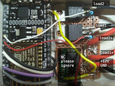
photo of dc converter load2 photo of ultrasonic for device

\$\endgroup\$
0

1 Answer 1

3
\$\begingroup\$

Q1) I would guess the cause is current taking a while to pass trough the high input impedance of the voltmeter, try connecting a resistor in parallel to see if results are more stable.

Fan: It only draws 0.3A and so the BDW93C would work just fine, as the fan has 3 pins, you switch the power and ground pins and leave the 3rd pin unconnected (pin for speed sensing)

Boost converter: this boost converter cant turn off completely, only stop boosting voltage. You can use an N-channel MOSFET controlled using a drive circuit.

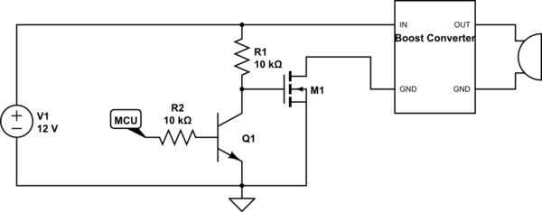
The reason for needing a drive circuit is that the MOSFET barely turns on with 3.3V, one circuit you can use is this:

schematic

simulate this circuit – Schematic created using CircuitLab

This has 1 problem, setting the MCU pin high will turn off the converter and setting it low will turn on the converter. Also if the mcu is not active, the MCU pin will float and the converter will turn on.

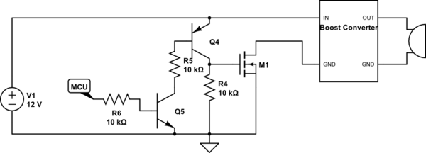
One way to fix this is:

schematic

simulate this circuit

This circuit uses both a PNP and an NPN however, it will prevent the MOSFET from turning on if the MCU isn't driving its output.

\$\endgroup\$
4
  • \$\begingroup\$ Incredible response time, thank you so much. I added photo of converter and indeed it has enable pin, I use them for years and didn't notice it. Found related answer electronics.stackexchange.com/a/308298 but am confused now if I have to modify converter. Adding 8k resistor as load of course fixes negative voltage at open state but still there is short burst to 17V at switch-on. \$\endgroup\$
    – temoto
    Commented May 27, 2020 at 10:02
  • \$\begingroup\$ Thank you, indeed I very much need both loads to be off by default, so the second circuit with two transistors is great. Any amount of additional components is not an issue at all. Would you please explain how MOSFET is better from current darlington switch? I lack electronic basics understanding but it seems right now two BDW93C switch both loads, including boost converter as expected. BDW93C spec says collector current 12A. Unsure how to read its safe operation graph. \$\endgroup\$
    – temoto
    Commented May 29, 2020 at 18:21
  • \$\begingroup\$ The darlington will switch 2A just fine, however, it will dissipate alot of heat and will require a heatsink, a basic mosfet will switch 2A just fine without a heat sink. \$\endgroup\$ Commented May 31, 2020 at 10:41
  • \$\begingroup\$ Thanks. I spent about 3 days learning about fets and circuits and in the end ordered high-side load switch module BTS740S2 with integrated protections. \$\endgroup\$
    – temoto
    Commented May 31, 2020 at 15:12

Your Answer

By clicking “Post Your Answer”, you agree to our terms of service and acknowledge you have read our privacy policy.

Not the answer you're looking for? Browse other questions tagged or ask your own question.