DAC aliasing isn't exactly the same as ADC aliasing.
Samples are just numbers, they don't exist in the analog domain. In order to convert samples to voltage, we need a circuit that will output a voltage corresponding to the right sample value, at the right time.
However, even if the circuit outputs the right value at the right time, what should it do "between" the samples? With sampled data in the digital domain, there are only samples, the concept of "what happens between the samples" does not exist.
So, aliasing in an ADC means there are an infinite number of signals that can alias down to the bandwidth of the sampled signal and produce the same result. If the input signal has energy outside of the bandwidth allowed by sampling frequency (cf. Nyquist) then frequencies outside of this bandwidth will alias into it and be indistinguishable from the actual frequencies we want to acquire with the ADC. Thus an input filter is necessary to remove out of band frequencies before sampling.
Aliasing in a DAC works in reverse: from a sequence of samples, it is possible to generate an infinity of different analog signals that all pass through the sample points, but "fill in the blanks" between samples in different ways. Some of these will have desirable characteristics, but others will not.
We could use a circuit that outputs a Dirac pulse at each sampling instant (plot below). Unfortunately, the spectrum of a Dirac pulse is infinite and does not fall off with frequency, so that just replicates tiles the original spectrum to infinity. This is also not a practical method, as Dirac pulses do not exist in the analog world.
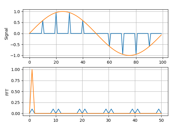
So we could use a Zero-order hold instead. This is identical to convolving the output signal of the previous circuit with a flat-top pulse whose width is one sample interval, and has the corresponding effect on its spectrum. Since time domain convolution corresponds to spectrum multiplication, the previous spectrum is multiplied by the spectrum of the pulse, which is a sinc.
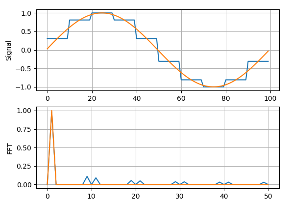
Note the FFT X axis is just the bin numbers, I didn't bother displaying the frequency. Anyway, with an ADC, input frequencies outside of your Nyquist bandwidth alias into your signal. With a DAC, they alias out, and the output signal always contains frequencies above Fs/2. So, just like an ADC needs an input filter, a DAC needs an output filter.
OK, this is not the question you asked...
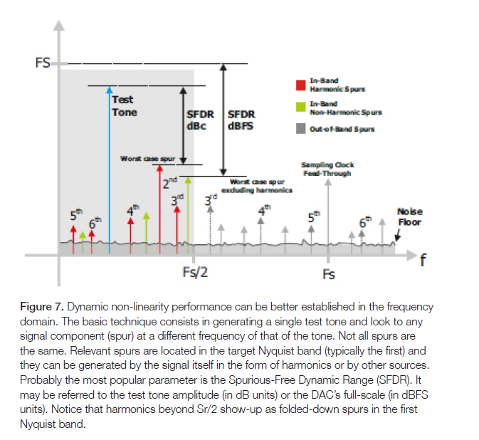
hen generating a single test tone with a DAC, harmonics of the fundemental frequency appear due to DAC nonlinearity, and if their frequency is higher than the Nyquist frequency (half of the sample rate), they fold down (alias) to the first Nyquist band.
Indeed they do. I'll use F as the signal frequency and Fs as the sampling frequency.
The sampled digital signal cannot contain harmonics above Fs/2. But suppose the digital to analog conversion generates high harmonics before the zero-order hold due to a nonlinearity in the multilevel DAC. At this point, the signal is still sampled at Fs. So the high harmonics do not appear as frequencies above Fs/2. Instead, they are sampled, just like they would be in an ADC running at Fs, and they alias back into the Nyquist bandwidth.
Here's an example: suppose we have a 1kHz signal sampled at 8ksps. There is a nonlinearity in the DAC that makes some harmonic 6. If the signal was not sampled, this would add some 6kHz to the 1kHz signal. However, in this case it is sampled, so the result is the same as sampling a 6kHz signal at 8ksps, which aliases it into the Nyquist bandwidth at the wrong frequency.
So this type of aliasing is similar to what happens in an ADC due to sampling, because the harmonics are generated before the zero-order hold, which in this case acts as a sampler, and aliases them back into the Nyquist bandwidth where they can't be filtered out.
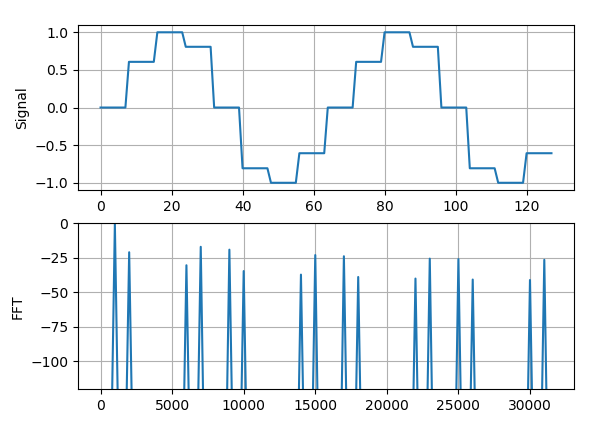
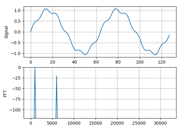
Let's make a 1kHz signal, add some 6th harmonic, and sample it at 64ksps: the output spectrum contains 1k and 6k (this time the X axis is correct).
...but if the output after the distortion is added is sampled at 8ksps, because the DAC works at 8ksps, then the distortion aliases back at 2kHz into the output spectrum.
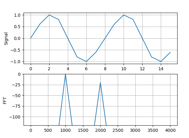
The actual DAC output signal would look like this, with zero order hold applied. That simply tiles the spectrum like puzzle pieces, and on each of these copies of the spectrum, the 6th harmonic is at the same frequency as the 2nd would be. A filter will get rid of the frequencies above Fs/2, but the part that aliased into the Niquist band is impossible to get rid of without also removing the signal.
