0
\$\begingroup\$

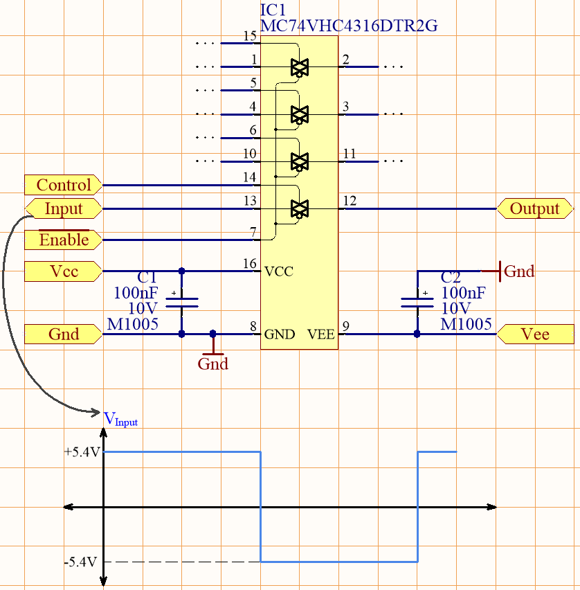
My Analog Switch Circuit

I have an analog switch circuit as seen in the image above.

I want to switch a digital signal which has either -5.4V or +5.4 level.

My analog switch is MC74VHC4316.

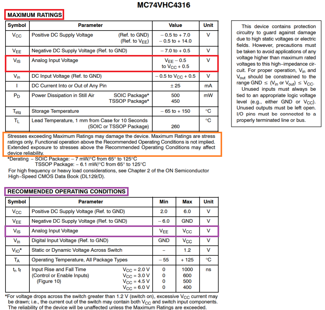
According to the datasheet, the VCC voltage can be in the interval of [+2.0V, +6.0V], and the VEE voltage can be between [-6.0V, 0V].

I understand that the internal impedance of the switch varies according the applied VCC and VEE voltage levels (see: datasheet, 4th page, 2nd table).

I want to know if I need to apply at least +5.4V VCC and -5.4V VEE voltages in order to transfer a \$\pm\$5.4V signal. What happens if I supply the IC with lower VCC and VEE voltages (e.g.; VCC = +3.3V, VEE = 0V). Does my digital signal get clamped? Does anything bad happens other than seeing a higher switch channel impedance?

\$\endgroup\$

1 Answer 1

1
\$\begingroup\$

The recommended operating conditions suggest your input signal should not be outside the power supply range. The absolute maximum ratings state that exceeding the power rails by more than 0.5 volts may damage the device (orange rectangle below).

enter image description here

I want to know if I need to apply at least +5.4V VCC and -5.4V VEE voltages in order to transfer a ±5.4V signal.

Yes that would be OK

What happens if I supply the IC with lower VCC and VEE voltages (e.g.; VCC = +3.3V, VEE = 0V). Does my digital signal get clamped? Does anything bad happens other than seeing a higher switch channel impedance?
You risk damaging the chip. However, if you limit the current drive capacity of your slightly excessive signal to significantly within the +/- 25 mA specified in the absolute maximum ratings, then this should be fine but, your signal will become clipped.

\$\endgroup\$

Your Answer

By clicking “Post Your Answer”, you agree to our terms of service and acknowledge you have read our privacy policy.

Not the answer you're looking for? Browse other questions tagged or ask your own question.