1
\$\begingroup\$

I have a microcontroller running at 5v and outputting a digital signal. This signal can be high, low or high-impedance (tristated).

This signal goes to an input pin on a target chip (the type of which is not known in advance), which may be running at 3.3v or at 5v. Therefore, I need some way to limit the "high" signal to the VCC of the target.

Ordinarily, I would use a level shifter, but they don't support tristate. I could use a tristate buffer, but that's a whole extra chip - not to mention the extra control pin.

Could I use a resistor?

I may be wrong, but I believe the "maximum input voltage" limitation on chips is due to current - often current through an internal protection diode. If I used a 10K resistor, surely so little current would flow into the input as to represent no danger to the target?

It did occur to me to use a resistor AND a diode to VCC, thus limiting the voltage to VCC+0.6v.....but might this cause issues with the tristating?

EDIT: Added diagram for resistor + diode. Would this work? Or would it cause issues with the tristating?

resistor and diode

Only problem I can think of is, in the absence of target VCC, it will be supplied a 4.4V VCC from the signal. So I would need to avoid setting the signal high when the target didn't have power applied. Am I right?

EDIT: Clarification:

I think perhaps some of you are misunderstanding the question. The output signal (at 5V, 0V or floating) has to be safe (and a valid high/low/hi-z) for all 5V and 3.3V targets, which are likely to be microcontrollers. Will my resistor-and-diode solution work? Or, will just a 10K resistor work?

\$\endgroup\$
7
  • \$\begingroup\$ Except that the target chip may be running at 5V, in which case, a resistive divider will be counterproductive. \$\endgroup\$ Commented Aug 10, 2020 at 15:25
  • \$\begingroup\$ The target chip can change. Hence my explicit disclaimer that the chip is NOT KNOWN AHEAD OF TIME. Your comment specifically instructs me TO know it ahead of time. \$\endgroup\$ Commented Aug 10, 2020 at 15:36
  • \$\begingroup\$ If the component has internal ESD clamp diodes you may use a series resistor to limit current through them. But rise/fall times will be affected. What does tristate have to do with anything? \$\endgroup\$
    – DKNguyen
    Commented Aug 10, 2020 at 15:43
  • \$\begingroup\$ And if the component doesn't have clamp diodes? (Tristate is needed for this project.) \$\endgroup\$ Commented Aug 10, 2020 at 16:07
  • \$\begingroup\$ Then you need to add some. I mean, what does tristate have to do with limiting voltages? \$\endgroup\$
    – DKNguyen
    Commented Aug 10, 2020 at 16:13

1 Answer 1

1
\$\begingroup\$

5V logic IC's without hysteresis usually have a Vih >=0.70 Vdd which at 5V >=3.5V but at -10% = 4.5V is 3.15V.

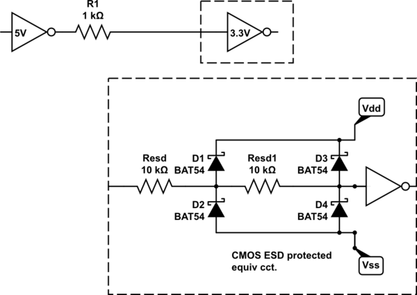
To limit Iin(abs. max) to target 3.3V device from 5V to 5mA even though many CMOS ESD protection diodes can handle 20mA, a series resistance may be included of (5-3.3)/5mA = 340 ohms and 1K to 10K may be used with a safety margin unless rise time is a major concern with < 5pF per gate.

Thus a simple solution is to choose a 5V driver with 1k series resistance added.

schematic

simulate this circuit – Schematic created using CircuitLab

Even though adding 1k appears to be redundant, it allows one to verify the action of the ESD protection on the 3.3V interface and Iih input current from measuring the voltage drop if you wish to verify using a 5V driver.

ESD dual-stage diode protection is what allows all CMOS which is universally designed to be protected with the Human Body Model, JEDEC: JESD22−A114 4kV 100pF discharge.

\$\endgroup\$
8
  • \$\begingroup\$ Will this solution work if the target chip is a 3.3V microcontroller? \$\endgroup\$ Commented Aug 10, 2020 at 17:58
  • \$\begingroup\$ Yes even 1.6V device \$\endgroup\$
    – D.A.S.
    Commented Aug 10, 2020 at 18:37
  • \$\begingroup\$ @TonyStewart The MSP430 (a CMOS device) cannot handle more than 2 mA via its protection diodes. The designer is responsible for limiting well below that. I can't say when I've seen a CMOS MCU that handles 20 mA in its protection diodes. Is there one? \$\endgroup\$
    – jonk
    Commented Aug 10, 2020 at 20:05
  • \$\begingroup\$ Yes there are gates that handle this in LVC series. 4000 series was 5mA and less indicates a smaller junction. That's why I chose a safety factor to get (5-3.3)/1k= 1.7mA max. One could easily justify increasing this value to 3k3 for short paths but path length was not specified. \$\endgroup\$
    – D.A.S.
    Commented Aug 10, 2020 at 20:35
  • \$\begingroup\$ This LVC inverter is even better rated at 50mA Abs Max input clamp current. ti.com/lit/ds/symlink/… 50mA*20kohm = 1kV \$\endgroup\$
    – D.A.S.
    Commented Aug 10, 2020 at 20:39

Your Answer

By clicking “Post Your Answer”, you agree to our terms of service and acknowledge you have read our privacy policy.

Not the answer you're looking for? Browse other questions tagged or ask your own question.