1
\$\begingroup\$

The design I have in mind will be battery operated, so I have found the TL972 (Datasheet Here) which only operates from 0 - 12 V. What I want this op-amp to do is to create a sawtooth/triangle wave generator to drive a VCO, namely the POS-535+ (Datasheet here). The frequency we want the VCO to output is around 300 - 400 MHz, and according to the figure named "Frequency and Tuning Sensitivity" in that datasheet, 2 - 7'ish volts will cover that output range of frequencies. (For the design, I want 1 - 8 V just to be on the safe side.

. . .

I have researched all over the Internet, but the only op-amps I am seeing that will generate the desired waveforms swing and operate from negative voltages. I have tried those circuits, to no avail.

Technically, I could use an LDO voltage regulator to output a negative voltage for an op-amp, but this will add more complexity/cost to the circuit and will be considered as a last resort.

So designing this circuit isn't too easy as first we have to make the first portion of the op-amp create a square wave, and then the other will create the ramp. I'm not entirely sure how to do that and would like help/pointers on doing so. Unfortunately, I have no schematics thus far for reference as all the schematics I have seen are for op-amps that operate between negative to positive.

. . .

Also, to generate a ramp wave of 1 - 8 V is pretty dang broad. If there is a better VCO that operates no more than 12 V and covers 300 - 400 MHz, please by all means recommend one to me if that is more convenient than designing a ramp wave that sweeps 1 - 8V.
Any help, guidance, or pointers is greatly appreciated! (Forgive my terminology if I misused some terms. Engineer in progress here.)

\$\endgroup\$
2
  • 1
    \$\begingroup\$ You're over-focusing on the opamp. If your circuit is "crap" no matter what opamp you use, the circuit remains "crap". So find solutions that would work for your application with an "ideal" opamp (so ignore the opamp's limitations). You appear to make your own life very hard by trying to solve (the wrong) issues. That's a sign of inexperience. That's OK, we've all been there. Take a step back and draw a rough block diagram or even a schematic of what you want to do. Post it here in the question and ask for input. \$\endgroup\$ Commented Sep 5, 2020 at 14:51
  • 1
    \$\begingroup\$ Also, 300 MHz is firmly in the range that I call "RF" so you need to "know what you're doing", if not things will simply not work. Actually the saw/triangle generator and the VCO are separate things so asking about both in the same questions isn't a good idea. Make one question for the generator and another for the VCO. But don't ask which VCO to use as that's a shopping question so it will be closed. \$\endgroup\$ Commented Sep 5, 2020 at 14:54

2 Answers 2

1
\$\begingroup\$

You've specified your VCO output frequency range but didn't specify the triangle / sawtooth wave frequency. I'm guessing that you're using this to sweep the VCO so it will be operating at a much, much lower frequency. If that's the case then all the 300 - 400 MHz info in your question is irrelevant.

enter image description here

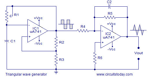
Figure 1. Square and triangle wave generation. (Don't use 741s. Use something modern.) Image source: Circuits Today.

In the case of the triangle wave you could use something like that of Figure 1 but instead of referencing R3 and R6 to battery negative you would generate a mid-supply reference and connect them to that.

schematic

simulate this circuit – Schematic created using CircuitLab

Figure 2. A mid-supply ground reference.

You'll see this solution used a lot in guitar effects pedals that run from a single 9 V battery but require AC swing about the "zero" reference internally.


Remember that op-amps don't have a GND pin. They only have a positive and negative supply so they don't care what your GND is as long as you give it adequate voltage between it's power pins and don't exceed the maximum input specifications.

\$\endgroup\$
1
  • \$\begingroup\$ +1 for Don't use 741s. Use something modern The 741 is RIP, it served us well, it's retired now. \$\endgroup\$ Commented Sep 5, 2020 at 14:57
0
\$\begingroup\$

Just so we're clear, there is nothing about that opamp that requires only a single supply.

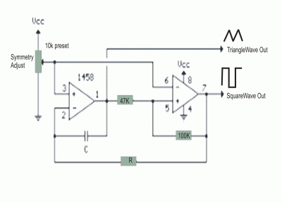
A problem with the previous schematic is that it requires that the time constants of the oscillator and integrator must track with time and temperature. If not, the integrator output amplitude will vary. Also, the integrator time constant must be short enough that the integrator output does not saturate before its input changes state. If you want to adjust the triangle wave frequency, at least two resistors must change.

Here is an alternate example schematic grabbed from the innergoogle. This one has a comparator instead of a squarewave oscillator, so the triangle output amplitude is independent of the operating frequency. The output amplitude is set by the comparator trip points; they can be set such that the triangle output never clips. And, only one resistor has to change to vary the circuit frequency.

enter image description here

\$\endgroup\$

Your Answer

By clicking “Post Your Answer”, you agree to our terms of service and acknowledge you have read our privacy policy.

Not the answer you're looking for? Browse other questions tagged or ask your own question.