2
\$\begingroup\$

I’m trying to control a motor that runs at 1.5v at ~0.5A using a Particle Photon. I’m powering the Photon over USB (for now, at least) and the motor with a AA battery. I’ve tried designs based off this schematic (modified to power the motor with the battery) but ended up with unacceptable noise in a separate circuit connected to the Photon. I’ve also tried this design without success. I’m a total noob at this stuff so any help would be appreciated.

I have an inexhaustible supply of resistors, a variety pack of transistors and diodes, some small capacitors, and PC817 optocouplers at my disposal (along with some other misc. components).

I’ve read this but most of it went over my head.

\$\endgroup\$
6
  • \$\begingroup\$ what's a particle photon? \$\endgroup\$
    – jsotola
    Commented Sep 13, 2020 at 6:19
  • \$\begingroup\$ @jsotola I think it’s optocoupler \$\endgroup\$
    – Chu
    Commented Sep 13, 2020 at 7:38
  • 1
    \$\begingroup\$ It's not an optocoupler. Particle Photon is a IoT board with WiFi connectivity and STM32 microcontroller. \$\endgroup\$
    – Justme
    Commented Sep 13, 2020 at 8:08
  • \$\begingroup\$ @Ezra, in English we use capital letters for proper nouns including names and brand names. This would make it clear that you are using a Particle Photon rather than a particle photon. Capitals matter! Can you edit the question title and your post to fix that? \$\endgroup\$
    – Transistor
    Commented Sep 13, 2020 at 9:17
  • \$\begingroup\$ @Transistor I’m a native english speaker, just on my phone and forgot to double check that 😬. Thanks for the catch! \$\endgroup\$
    – Ezra
    Commented Sep 13, 2020 at 14:12

1 Answer 1

2
\$\begingroup\$

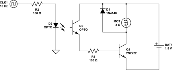
fortunately the noise of a motor with these specs is easy to control. the figure 5.2.5 in the second link, works fine. but I assume you have connected both grounds together. it should be connected like this :

schematic

simulate this circuit – Schematic created using CircuitLab

this way, there is no physical connection between motor control and logic circuits. but there are some notes:

  • a tiny relay would work without much hassle.
  • the transistor should withstand at least 1amps for a safe margin.
\$\endgroup\$
2
  • \$\begingroup\$ Just to double check- this should work with a PC817? I realized I forgot to include the exact part I have in my question. \$\endgroup\$
    – Ezra
    Commented Sep 13, 2020 at 14:08
  • \$\begingroup\$ @Ezra yes it works with PC817 and many other transistor output opto-isolators. \$\endgroup\$ Commented Sep 13, 2020 at 14:12

Your Answer

By clicking “Post Your Answer”, you agree to our terms of service and acknowledge you have read our privacy policy.

Not the answer you're looking for? Browse other questions tagged or ask your own question.