1
\$\begingroup\$

I am driving / modulating a small laser LED module LC-LMD-650-01-03-A (3.3V @ 25mA). My job is to PWM modulate it at 10kHz for 50msec, driving it with DSPIC33CK256MP503 (3.3V) dsPIC processor.

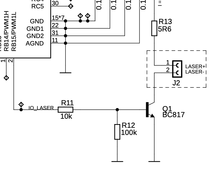
First I was just switching it using an NPN transistor, which acted as a simple open collector switch. PIC was pulsating its base, the emitter was on ground and the laser diode module was in its collector as load. My problem was the laser turned on strong and fine, but when the transistor closed, the laser was turning of slowly due to its internal circuitry. I needed to come up with some way to quickly turn it off.

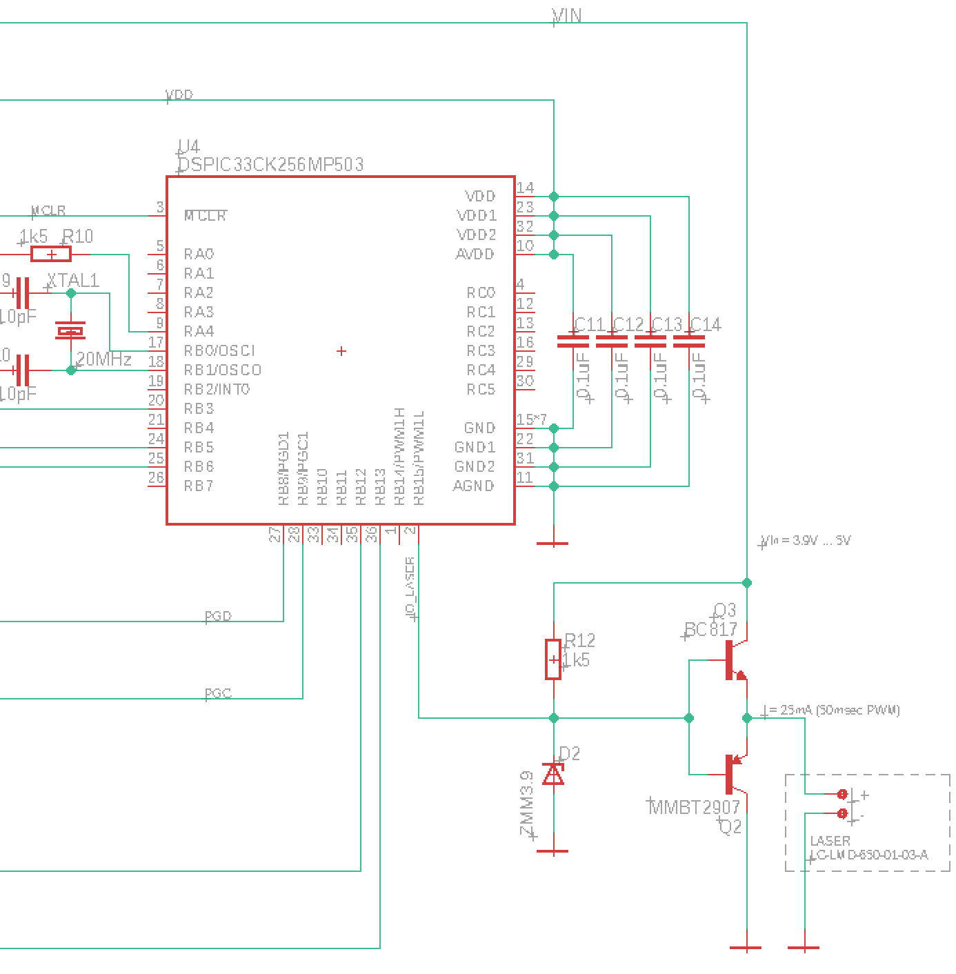
So I used a standard NPN/PNP push-pull circuit, which I attached directly to my 5V battery source, before the 3.3V LDO regulator.

Now the laser modulation worked. Receiver recognized it, but the laser was too dim. Reason was clear, the push-pull circuit output is always about 0.6V less than its base input, which is driven by my 3.3V processor I/O output pin. Laser diode was only getting about 2.5V instead of desired 3.3V, regardless what was the voltage powering the push-pull circuit.

My selected I/O pin happens to be 5V input tolerant.

My question is, can I just switch my I/O pin to be open drain, and attach it to increased voltage by using a Zener diode, as on attached picture? The goal is to have 3.9V on the push-pull base, giving it the desired output of 3.3V.

enter image description here

UPDATE: After @AndyAka suggested to go back to open collector NPN, just to modify it, I am adding here my original first schematics section in order to continue the discussions.

enter image description here

\$\endgroup\$

1 Answer 1

2
\$\begingroup\$
  • When driving a laser never turn it off to 0 mA because the recovery time for it to start emitting light is too long.

  • When driving a laser respect the upper limit of current it can take just as you would when using an LED

Your first circuit with the NPN transistor would work if you had a resistor in series with the NPN emitter to ground. This would prevent overcurrent of the laser (and laser failure). Then you need to ensure that you do not fully turn off the NPN when logic level 0 is present. You would need to bias the drive level to the NPN's base to ensure this happens properly.

I can't tell you where to bias this but I would estimate that laser currents of 5 mA for logic 0 and 25 mA for logic 1 would be a good starting point.

\$\endgroup\$
6
  • \$\begingroup\$ Andy, I updated the question so you can see the original schematics. Are you saying, that I should go back to that and add a resistor between emitter and ground? (I already have a footprint for a series resistor R13 above laser diode, can I use that to save existing PCBs? I understand its value must be calculated to assure max 25mA). 2) can you please explain a bit the turning OFF? \$\endgroup\$ Commented Sep 19, 2020 at 11:26
  • \$\begingroup\$ The proper circuit would use an emitter resistor. What do you need explaining about the turning off that hasn't been covered in my answer? \$\endgroup\$
    – Andy aka
    Commented Sep 19, 2020 at 11:54
  • \$\begingroup\$ I must admit, I am not good enough to figure out the bias resistors in this case, when there are two voltage sources, that is what I mean to please help explaining: I CAN bias with 2 resistors creating a base divider, then connect let's say 18 Ohm resistor to emitter to have a constant current generator, as you suggested. But I CANNOT figure out how to calculate additional CPU pin connected to the base, with its own resistor, to pre-set 5mA. Now I have three unknown resistors, and two known desired base voltage levels (0.69V makes 5mA; 1.05V makes 25mA in case of 18 Ohm resistor) \$\endgroup\$ Commented Sep 19, 2020 at 14:31
  • 1
    \$\begingroup\$ Start with a 100 ohm emitter resistor. Then, when the base is pulled up to 3 volts you get about 23 mA through the laser. Make that pull up via (say) 1000 ohm and the current will still be about 23 mA. Then, when the IO connects to the base via (say) 560 ohm, AND the IO is at 0 volts, the voltage on the base will be about 3 volts * 560/(1000+560) = 1.08 volts and this should reduce the laser current to about 4 mA. \$\endgroup\$
    – Andy aka
    Commented Sep 19, 2020 at 15:31
  • 1
    \$\begingroup\$ of course! two resistors only, easy calculation! I was calculating an additional resistor between B-E, which is not needed. This makes your above answer complete for sure, thank you. \$\endgroup\$ Commented Sep 20, 2020 at 8:32

Your Answer

By clicking “Post Your Answer”, you agree to our terms of service and acknowledge you have read our privacy policy.

Not the answer you're looking for? Browse other questions tagged or ask your own question.