2
\$\begingroup\$

I am required to design a class AB audio amplifier to deliver 10W to an 8Ω speaker as shown, but I don't know where to start. The bandwidth is to cover the range from 20Hz to 18kHz. Input voltage is 500mV rms.

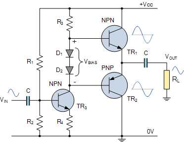
enter image description here

circuit diagram

Image source: Electronics Tutorials - Class AB Amplifier Driver Stage

This is what I have done so far

CALCULATIONS.

  • R_L = 8 Ω

  • P_AVG = 10W

  • Bandwidth from 20 Hz to 18 kHz

  • V_(0 peak) = √(2×10×8) = 12.65v

  • V_CC = V_(0 peak)×2+2 = 27.3V ≅ 28V

  • I_(0 peak) = V_(0 peak)/R_L = 12.65/8 = 1.58A

Each transistor current is given by:

  • I_(0 peak)/2 = 1.58/2 = 0.79A

Assuming β = 113

  • I_(B Q1) = I_(B Q2) = I_E/(β+1) = 0.79/114 = 6.93mA

Assuming I_D = 1A, then:

  • I_bias = 1mA+1mA+6.93mA+6.93mA = 15.86mA

Setting V_C = 14V, then:

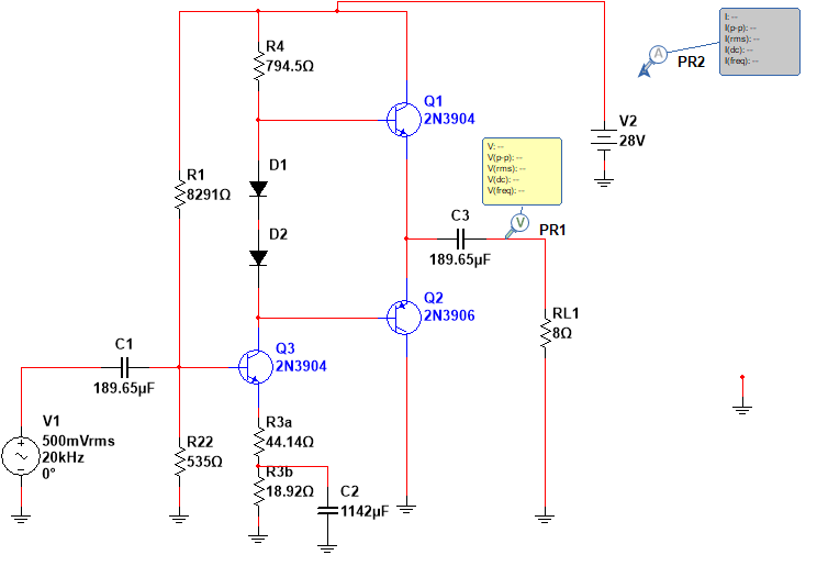
  • R4 = (28V-14v-0.7v-0.7V)/15.86mA = 794.5Ω

Setting V_E = 1V

  • R_3+R_3^II = 1V/15.86mA = 63.05Ω

Input current is assumed to be 500mA Q_3 gain is given by:

  • V_(O peak rms)/V_(in rms) = √(8×10)/500mA = 17.88Ω

Setting Q_3 gain to 20:

  • R_3^II = ((28V-14V)/15.86mA)/20=44.14Ω
  • R_3=63.05-44.14 = 18.92Ω
  • I_B = I_C/β = 15.86mA/100 = 0.1586mA

Setting I_1 = 20 I_B:

  • I_B = 20×0.1586mA = 3.172mA
  • R_2 = 1.7V/3.172mA = 535Ω
  • R_1 = (28V-1.7V)/3.172mA = 8291Ω

Designing for C_1 and C_3:

  • r_e = 26mV/15.86mA = 1.64Ω
  • R_1 ||R_2 = 502.57Ω
  • R_3^II = 44.14Ω
  • R_th = 41.96Ω
  • C1 = C3= 1/(2×π×f_L×R_th) = 1/(2×π×20×44.14) = 189.65μF

Designing for C_2:

  • R_th = 69.6759Ω
  • C_2 = 10/(2×π×f_L×R_th) = 10/(2×π×20×69.6759) = 1142μF

When I simulate the circuit, the output voltage is quite small and the output power is much less than 10W.

What could be the issue?

The final circuit I came up with is shown.

\$\endgroup\$
12
  • 2
    \$\begingroup\$ Is this homework? What have you tried so far? \$\endgroup\$
    – Reinderien
    Commented Oct 27, 2020 at 16:12
  • 10
    \$\begingroup\$ What are you stuck on? We can't help you if we don't know the specific problem you're having. Why don't you you show your work so far, or if you just can't start at all, say what your own personal brick wall looks like. \$\endgroup\$
    – TimWescott
    Commented Oct 27, 2020 at 16:12
  • 2
    \$\begingroup\$ Well, you have started -- you've asked for help. So -- what do you know about circuit design so far? What's the class? Do you know what "10W into 8\$\Omega\$" means? Can you look at the schematic and see how that circuit might work? \$\endgroup\$
    – TimWescott
    Commented Oct 27, 2020 at 16:17
  • \$\begingroup\$ I got Vo peak as √(10*8*2) which gives 12.65v.I then set Vcc=Vo peak*2 +1 which gived 27v. \$\endgroup\$ Commented Oct 27, 2020 at 16:22
  • 3
    \$\begingroup\$ I am a bit concerned -- if you know the load current, you should be able to immediately jump to the collector current, and from there -- plus maybe some transistor data sheets -- the base current. What is the class? Because either you've been sleeping, or the professor is forcing a really big jump on you. \$\endgroup\$
    – TimWescott
    Commented Oct 27, 2020 at 21:28

4 Answers 4

2
\$\begingroup\$

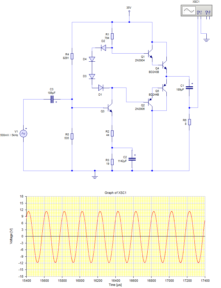
Your output transistors are small signal transistors, not power transistors.

The base currents of your output transistors are loading the common emitter amplifier's output down and reducing the gain.

I have added a power output stage and the required extra two diodes for biasing. Also increased the power supply voltage a little to prevent clipping.

Power amp simulation

\$\endgroup\$
2
  • \$\begingroup\$ Is it possible to just replace the output transistors with power transistors entirely? \$\endgroup\$ Commented Oct 28, 2020 at 21:12
  • \$\begingroup\$ I tried that and because the power transistors' hFE is quite low, the base currents are still quite large and it still loads the output down. However the simulation worked well with power Darlington transistors. I used TIP120 & TIP125 with good results. \$\endgroup\$
    – user173271
    Commented Oct 28, 2020 at 21:17
7
\$\begingroup\$

For 10 watts into 8 ohm speaker, you can do this system design

  • P = Vrms * Vrms / Rload

  • 10 watts = V * V / 8

  • 10 * 8 = V * V thus Vrms_out ~~ 9 volts RMS, or 2.828 * 9 peakPead

You will need headroom. So have at least 40 volts VDD.

Now for the gain:

The topology of common_emitter amplifier, into a resistive load, has maximum voltage gain of VDD / 0.026; with 40 volts / 0.026 (or 40 * 39) , the maximum gain is nearly 1,600. You only need 9_rms/0.5_rms or 18X.

Now for the load on the collector. That is heavy. Many milliAmps, because of 1 amp+ Iout, and moderate beta of the two output transistors. One amp / Beta = 100 ==> Ibase of 0.010 amp = 10mA.

What to do? The base currents will tend to cancel, so assume 10mA (net) into the two output transistors. And assume another 10mA to provide pullup to the +40 volts. So plan to operate that first transistor at 0.020 amps.

WIth 20mA Icollector and 40 volts, the maximum power dissipation of your first transistor (that common emitter) will be 20mA/2 * 40 volts/2 (for passive loads), or 10mA * 20Volt = 0.2 watts.

So you need a transistor in the voltage amplifier (gain of 9/0.5 = 18x) able to dissipate 0.2 watts. Probabaly don't worry about that yet.

How to design that first (voltage gain) stage?

\$\endgroup\$
3
\$\begingroup\$

but I don't know where to start

Every design process starts with listing the requirements. It appears that you've listed those, so that's a start.

A Class-AB audio amplifier involves three stages:

  • Input stage
  • Voltage Amplification Stage
  • Output stage.

And the design of each stage requires:

  • Basic circuit theory,
  • Transistor-based amplifier design,
  • Filter design,
  • And even a very basic understanding of feedback theory.

So, as you can see, a Class AB audio amplifier is not a "how can I design one?" thing. And it's almost impossible to learn how to design one from a simple answer posted here, believe me. We don't know your level of each topic above. If you had shown what you have tried so far then it would give a clue about your level and I'm sure that the experts here would show you where/what you did wrong and how to fix. For example,

I got Vo peak as √(10 * 8 * 2) which gives 12.65V. I then set Vcc=Vo peak*2 +1 which gives 27V.

You can't just put that +1V headroom randomly.


Note to the mods: I know that this is not an answer. But it'd be too long to put in the comments. So please don't hit me!

\$\endgroup\$
1
  • 1
    \$\begingroup\$ The design shown looks so classic, though, that I bet there will be many cookie-cutter dimensioning tables around that make the right assumptions for medium quality audio use :) \$\endgroup\$ Commented Oct 28, 2020 at 9:11
3
\$\begingroup\$

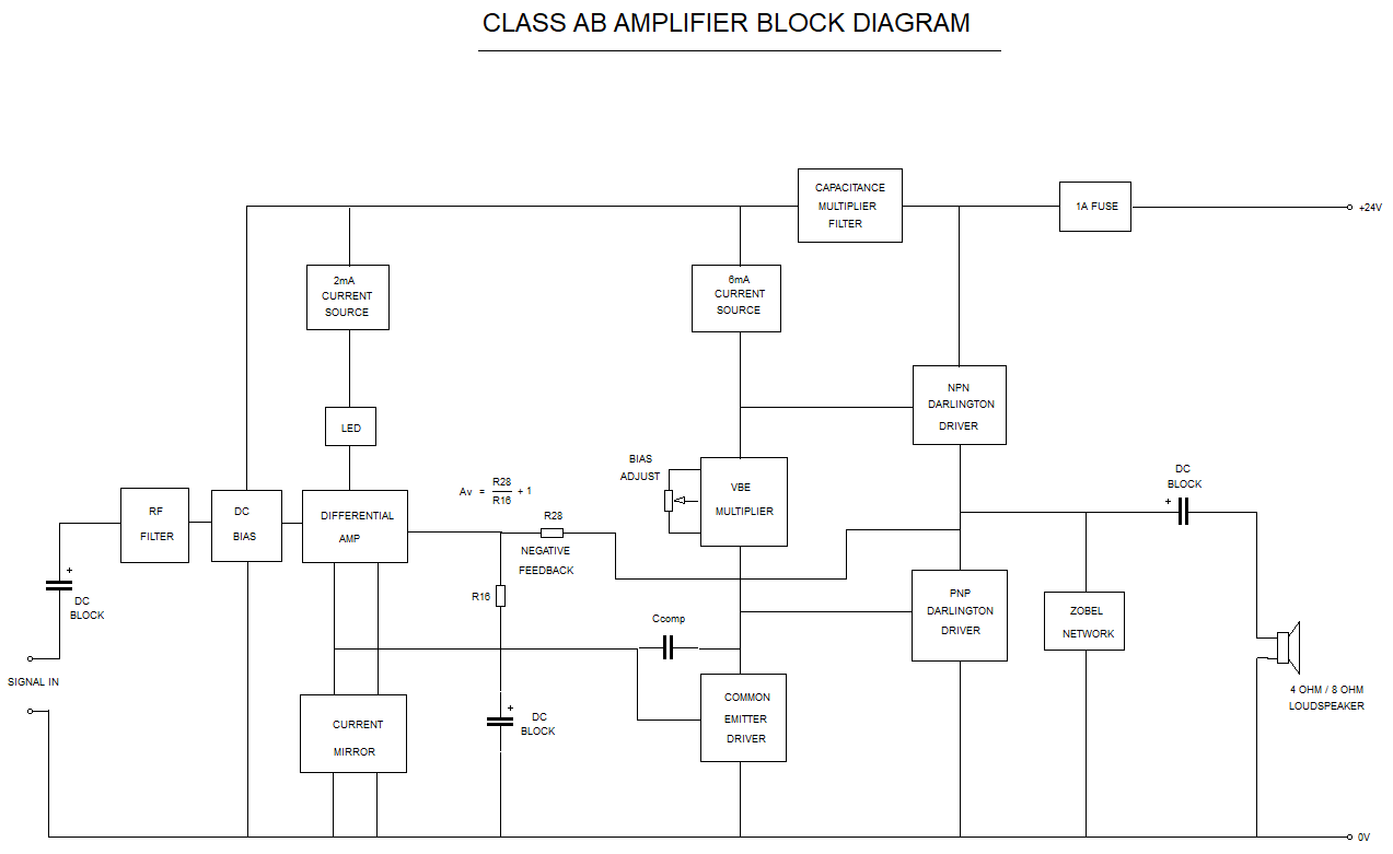
Overview block diagram of single supply class AB amplifier. This is representative of a 4W into 8R amplifier which I built and so the shown 24V supply would be too low for your requirements.

Block Diag of Class AB Amp

\$\endgroup\$

Your Answer

By clicking “Post Your Answer”, you agree to our terms of service and acknowledge you have read our privacy policy.

Not the answer you're looking for? Browse other questions tagged or ask your own question.