1
\$\begingroup\$

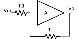
I have an amplifier in a closed loop, the diagram looks as follows:

Inverting amplifier

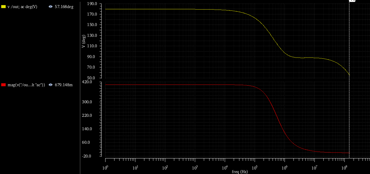
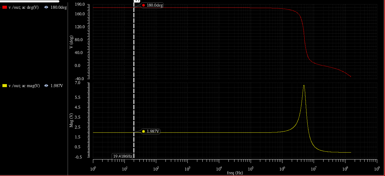
The DC gain is simple which \$ -Rf/R1 \$. If I make \$ -Rf=2\cdot R1 \$ the the DC gain is two. This is verified using AC analysis in Cadence. Closed loop gain phase

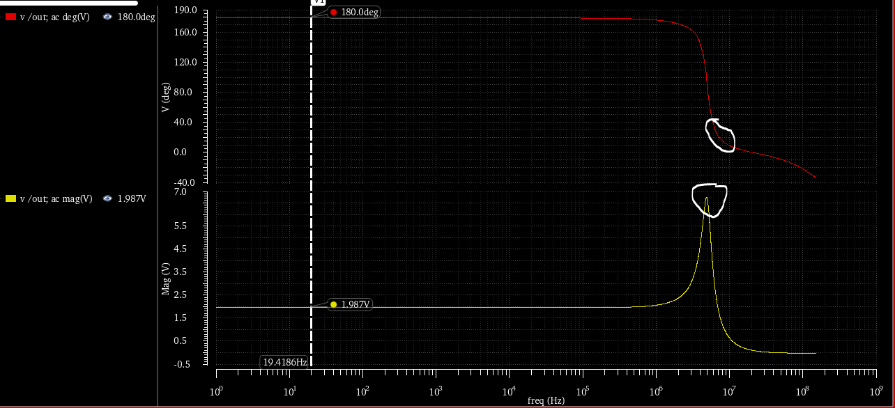
However there seems to be a complex conjugate pole also, which leads to unstable behavior. Location of complex conjugate poles

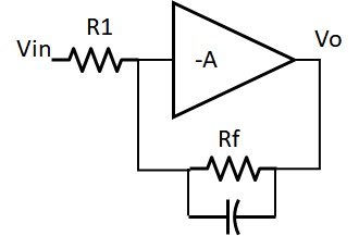
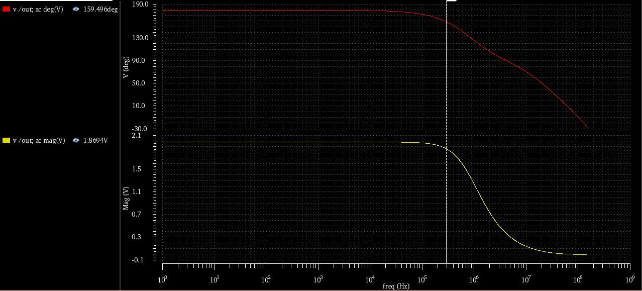
Hence I modify the gain equation as: \$Av= \frac{-Rf}{R1} \cdot \frac{1}{(s+\sigma + j\omega)(s+\sigma - j\omega)} \$. The notation \$ + \sigma \$ is because the phase goes negative. I observed that if I put a capacitor across Rf as shown in this figure then I can get rid of the complex conjugate poles. The value of capacitor is 1pF. Compensated gain and phase inverting amplifier with a compensation cap

So now the gain equation becomes: \$ Av= \frac{-Rf}{R1 \cdot C} \cdot \frac{1}{(s+\sigma + j\omega)(s+\sigma - j\omega)(s+p1)} \$ where \$ p1= 1/Rf\cdot C \$ This equation checks out because at DC, the gain is \$ -Rf/R1 \$.

My question is, from this equation how is the pole being compensated? Is my analysis even correct?

To add more information the open loop gain of the amplifier is a single pole system as shown here:

Open loop gain phase

\$\endgroup\$
4
  • \$\begingroup\$ At least a couple of things wrong here. It seems you place a 2nd order transfer function outside the loop, so it cannot possibly influence stability. Same argument for the 1st order pole. \$\frac{R_f}{CR_1}\$ makes no sense as a gain. \$\endgroup\$
    – Chu
    Commented Nov 14, 2020 at 13:57
  • \$\begingroup\$ @Chu I did not understand what did you mean by placing the 2nd order transfer function outside the loop. Please can you elaborate? \$\endgroup\$
    – RAN
    Commented Nov 15, 2020 at 8:35
  • \$\begingroup\$ From your equations the 2nd order function, and the 1st order function, are outside the op amp feedback loop. \$\endgroup\$
    – Chu
    Commented Nov 15, 2020 at 15:31
  • \$\begingroup\$ Yes there is no feedback loop inside the amplifier, it is open loop, is that what you meant? \$\endgroup\$
    – RAN
    Commented Nov 16, 2020 at 16:06

2 Answers 2

1
\$\begingroup\$

To clarify, the phase scale on the graphs represents by how many degrees the output signal leads the input signal. So the lead starts at 180 degrees and reduces as frequency increases. That is to say the closed loop lag starts at 180 degrees at dc and increases towards 360 degrees as frequency increases.

By placing a capacitor across the feedback resistor you are adding a closed loop pole. This rolls off the closed loop gain at a lower frequency but also introduces some extra closed loop lag. It is apparent how in the third graph the lag starts to increase at a lower frequency. (The closed loop lead has reduced).

But you might think, hey wait a minute, extra lag means a reduction in phase margin and reduced stability.

What is important to remember is that it is loop gain and phase that determines stability, not closed loop gain and phase. That closed loop pole that you have introduced by adding the feedback capacitor is actually a zero in the loop response. A zero in the loop increases loop gain which reduces phase margin (which reduces stability) but the more significant contribution from the zero in the loop is that phase lead is actually added to the loop increasing phase margin which increases stability.

To understand this it can be seen that the added capacitor reduces the feedback impedance as frequency increases thereby reducing the closed loop gain and adding a lower frequency closed loop pole, but going around the loop from output back to input, as the feedback resistor is gradually shorted out with increasing frequency, the loop gain is gradually increased. That is to say there is a zero added with its loop phase lead benefit.

EDIT

Your open loop response plots don't seem to be correct. A single open loop pole amplifier would have a minimum of 90 degrees phase margin and would be very stable with no peaking in the closed loop response. Peaking in the closed loop response and complex poles co-exist together and require a low phase margin, much less than 90 degrees. To get the peaking you are seeing I would expect the open loop response to have at least 2 poles in order to get something approaching 180 degrees open loop lag with the resulting closed loop peaking at low closed loop gains.

By adding the capacitor across the feedback resistor you are improving phase margin by adding a zero to the loop with its resulting added loop phase lead. I would now expect the closed loop transfer function to contain two real poles in its denominator, one caused by the capacitor rolling off the closed loop gain and a second created where the closed loop response meets the open loop response after its second pole where it will be falling at between -6dB/octave and -12dB/octave. If the meeting of the curves occurs nearer the -6dB/octave gradient than the -12dB/octave gradient then there will be sufficient phase margin to keep the poles real. In this scenario there will be no peaking in the closed loop response and therefore no complex poles.

To determine the actual closed loop transfer function which will depend on the size of the feedback capacitor you would need to determine the open loop transfer function, Ao and then derive the closed loop transfer function from Ao/(1 + BAo) where B is the frequency dependent feedback fraction. The resulting maths drill down will show you whether the closed loop poles are real or complex.

If the falling closed loop response (actually the 1/B) curve meets the open loop response curve where it is nearer -12dB/octave then the phase margin will be too small, there will be complex poles and peaking in the close loop response. This could happen when the feedback capacitor is sized too large. In this scenario the closed loop gain rolls off too early, the closed loop gain (actually 1/B) levels off at unity creating a pole in the loop, adding loop phase lag which cancels out the zero's loop phase lead leaving the loop response with increased gain and too small a phase margin.
\$\endgroup\$
4
  • \$\begingroup\$ The last paragraph in your answer makes sense, that the closed loop gain reduces as Rf is shorted out. But why isnt it apparent from the equations which I put in my question? The way i see it is, the complex conjugate poles are not really cancelled, but they are masked by a stronger dominant pole introduced by the feedback capacitor. Am I correct? Also please can you comment on the analysis I have shown? Are the transfer functions correct? \$\endgroup\$
    – RAN
    Commented Nov 15, 2020 at 8:48
  • \$\begingroup\$ @RAN See edit.. \$\endgroup\$
    – user173271
    Commented Nov 15, 2020 at 17:09
  • \$\begingroup\$ There are two poles in the open loop response, but the second pole is further away than the unity gain frequency, hence I have approximated the open loop response of that of a first order. The open loop second pole is not close to the closed loop peaking response. \$\endgroup\$
    – RAN
    Commented Nov 16, 2020 at 16:04
  • \$\begingroup\$ Also in the open loop transfer function which I have posted, the phase changes by 90 degrees, then it trails off to 180 degrees due to the second pole, which is already at very high frequency \$\endgroup\$
    – RAN
    Commented Nov 16, 2020 at 18:31
0
\$\begingroup\$

One common cause for the pole is: capacitance on the Virtual Ground of the opamp.

With high_value resistors, the DELAY on Virtual Ground, becomes large, and you get ringing or oscillation.

The feedback capacitor can be viewed as part of a voltage_divider with the VirtualGround capacitance. Thus at high frequencies, the delay is removed.

\$\endgroup\$
1
  • \$\begingroup\$ The reason for high value resistors is to not load the output stage of the amplifier. Besides I tried with lower values following your suggestion to no avail. \$\endgroup\$
    – RAN
    Commented Nov 15, 2020 at 8:53

Your Answer

By clicking “Post Your Answer”, you agree to our terms of service and acknowledge you have read our privacy policy.

Not the answer you're looking for? Browse other questions tagged or ask your own question.