4
\$\begingroup\$

I've been stuck on (what seems to be) a very unusual issue with a little audio circuit I’m designing. I wonder if anyone here can quickly highlight the flaws of my design and/or offer an insight into what’s going on.

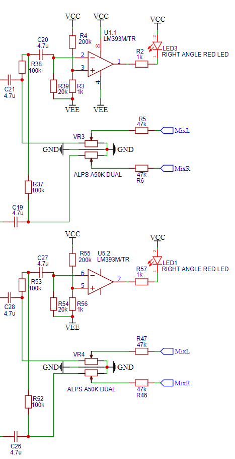
So, the issue is as follows. The circuit pictured below is a simple pair of comparators (LM393) indicating a 'healthy' signal level going into the two respective stereo inputs of an audio mixer. The LEDs illuminate and indicate signal as expected. The issue arises with the second channel, using comparator U5.2. When there is a strong enough signal to illuminate the LED it couples what I would call a 'breakthrough' noise onto my mix bus, which is very unpleasant at high gain levels (the noise is post-channel fader so cannot be faded out). For example, if the music had a strong drum beat each transient would couple a pop/click onto the mix bus.

I cannot work out why this is happening. In an attempt to fault find I wired the IC to swap the two comparators inside the package across the two channels and the fault moves (keeping all external components the same per channel), i.e. the top channel bleeds through distortion and the bottom channel is now clean. This left me very confused as it almost seems like any intrinsic flaws in the circuit are only bad enough to cause the second half of the comparator to misbehave. I also swapped in different manufacturers ICs and this made no difference.

I have not been able to fully understand the mechanism that couples these breakthroughs to the mix bus with my simple test equipment, so I am asking here in a hope that someone more intelligent than I can help.

Many thanks.

Output signal indicators

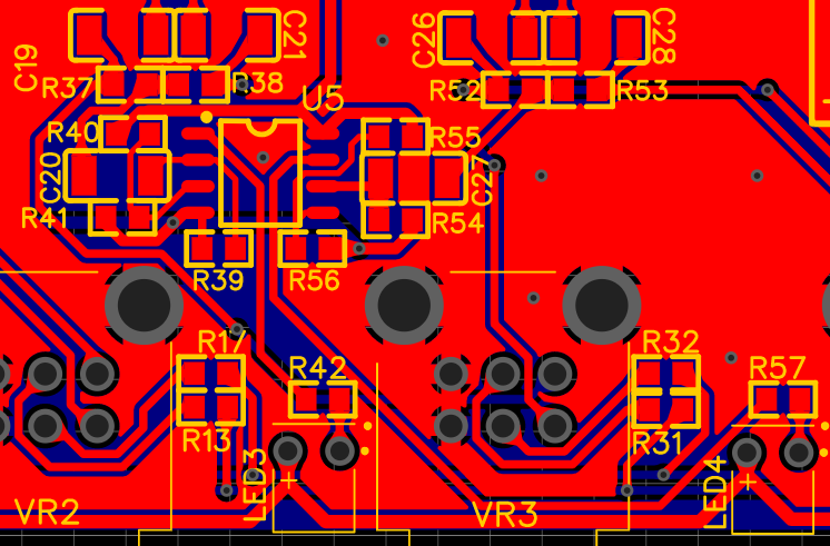
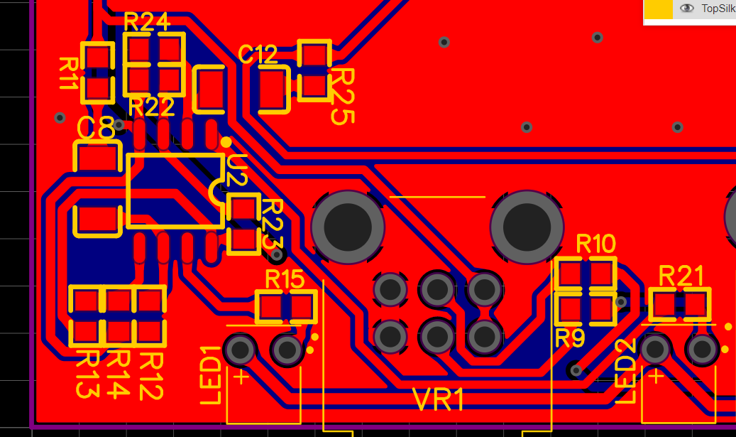
EDIT: I'm adding my PCB layouts below. In both cases the side of the comparator which has the longest trace to the LEDs current limiting resistor is the one at fault (R42, R57 / R15, R21). I will try to reduce the trace length and see if that makes a difference.

Layout 1

Layout 2

\$\endgroup\$
10
  • 1
    \$\begingroup\$ See if it persists if you disconnect the LEDs. Do you have bypass caps on the power rail of the comparator? What's your supply routing like, especially to the LED? \$\endgroup\$ Commented Nov 20, 2020 at 16:10
  • 1
    \$\begingroup\$ If the LED is diconnected the noise stops, so it must be the current through the led coupling. I have a bypass cap from VCC to VEE, do you think I should bypass to ground? LED supply is routed through a thick trace to all 4 LEDs across the front of a small PCB, so I cant see any issue there. \$\endgroup\$
    – Edd_P
    Commented Nov 20, 2020 at 16:18
  • \$\begingroup\$ Aside, make sure you're not violating any of the data in LM393 datasheet section 7.3 Recommended Operating Conditions. Seems input range is very specific: 0.0 or -0.1v to VCC-2v, with 20/25mA output max. \$\endgroup\$
    – rdtsc
    Commented Nov 20, 2020 at 16:22
  • \$\begingroup\$ It could be the LED current through the comparator, it could also simply be the current from the supply. You may need to partition off the LED driving, give it its own supply capacitance that feeds only an LED driver, coupled to the rest in a way that lowpasses it. \$\endgroup\$ Commented Nov 20, 2020 at 16:23
  • 1
    \$\begingroup\$ If all else fails, try adding a taste of hysteresis to the comparators such as 4.7M from pin 7 to pin 5 and 1 to 3. It's possible it's "singing" at the transition point, possibly due to bad layout coupling LED current back to the other input through some voltage drop. \$\endgroup\$ Commented Nov 20, 2020 at 16:40

1 Answer 1

1
\$\begingroup\$

The output of the comparator will swing many volts with a distorted version of the audio input signal. It will have very fast rise times that can easily couple though stray capacitance to other parts of the circuit.

I would suggest putting a capacitor of a few microfarads from the output of the comparator to ground. A small resistor (eg 47 ohm) in series with the comparator output will limit the current when discharging the capacitor.

That will do two things;

  1. When triggered the comparator will discharge the capacitor via its open-collector output and stretch the signal so that it will light the led brighter than the very small duty cycle that you currently have.

  2. The output signal will now change slowly and not couple into the audio output signal.

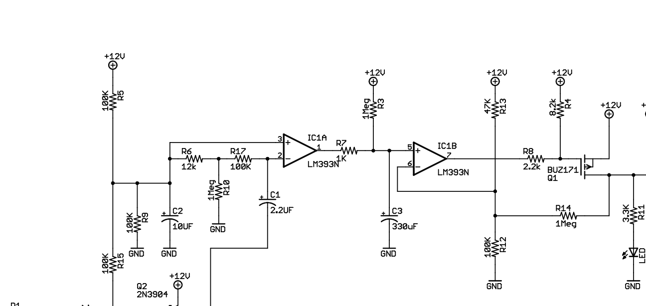
I use an almost identical circuit to turn on my power amplifier in a house audio distribution system for the last ten years. Audio switch

\$\endgroup\$
4
  • \$\begingroup\$ Hi Kevin, thank you for your input. Firstly I don't think this is a very good idea as every time the comparitor pulls low the capacitor will dump a large current through the device greatly overshooting its maximum rated sink current. Furthermore this capacitor is not required in the other circuit (the other half of the same IC) for proper functionality. \$\endgroup\$
    – Edd_P
    Commented Nov 20, 2020 at 18:59
  • \$\begingroup\$ @Edd_P - actually it doesn't as there is very little time between two cycles. A small resistor (eg 100 ohms) in series with the output will limit current. Although the other side is not causing trouble, it is just waiting for you to modify the wiring slightly (eg you decide to put the LED on a front panel) and the interference will come back. It will also increase the intensity of the LED as it will operate at more than 50% duty cycle and respond better to shor transients. \$\endgroup\$ Commented Nov 20, 2020 at 20:24
  • \$\begingroup\$ The datasheet for the LM393 comparator says in Note2 its maximum shorted-to-the-supply output current is 20mA and is safe continuously unless it overheats the IC. Your circuit is missing important hysteresis that is mentioned in the datasheet. \$\endgroup\$
    – Audioguru
    Commented Nov 22, 2020 at 20:09
  • \$\begingroup\$ @Audioguru - agreed hysteresis would be good to use but If the output has a capacitor to ground there is not a good signal to feed back from some the delta voltage at the output of comparator is extremely small. In the attached circuit you will see I have hysteresis on the level detector using the other half of the comparator - this is arranged to have a delay time of about 5 minutes before turning off the power amplifier. \$\endgroup\$ Commented Nov 22, 2020 at 23:24

Your Answer

By clicking “Post Your Answer”, you agree to our terms of service and acknowledge you have read our privacy policy.

Not the answer you're looking for? Browse other questions tagged or ask your own question.