2
\$\begingroup\$

First of all, I am going through designing all of this because I did not find a ready made circuitry for my purpose which is mentioned later. If you know a circuitry that is well tested and does what I want, by all means share it.

So I have this circuit:
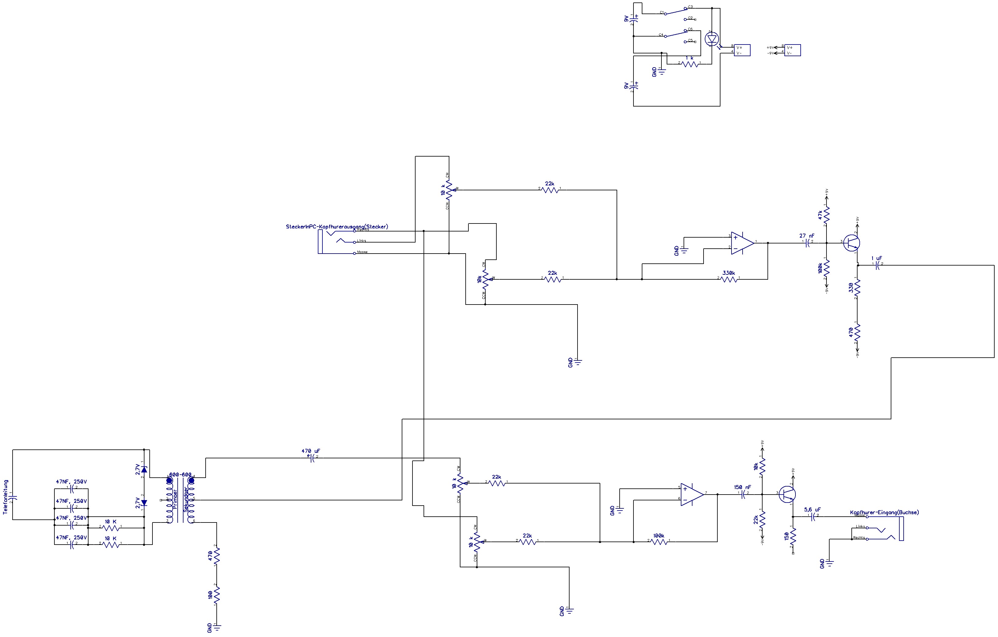
Schematic

Bigger picture

It is a computer-soundcard <-> telephone interface with Headphones to monitor.

Power supply is to be a symmetric 9V Power supply. PC Speaker(top-left) is the headphone output jack. The hum is in the headphones(bottom-right).

Two problems:

  1. When connection to PC speaker is plugged in and Telephone connection(bottom-left) is plugged in, I hear humming in the headphones. When only one is plugged in I hear it without distortion. Sound files showing humming.

  2. (Solved) When playing audio, it is almost not audible on the telephone side, ie, the person I am playing it to cannot hear it.

Please share ideas on how to solve the issues.

If you criticise my circuitry, add something to act as a replacement, too. Just saying that it won't work because of this and that is not as helpful as saying: "It won't work because of X, which is why I recommend doing Y". I try to update this question with the current circuit so you don't have to scroll through all replies to get the current status.

PS: Circuitry for telephone connection taken from a recording interface from Tekniikan Maailma magazine. I chose it to be able to use the circuit in parallel with my current phone.

\$\endgroup\$
10
  • 1
    \$\begingroup\$ Please include power supply details in your schematic. What exactly is GND? Are the op-amps on a dual voltage supply? \$\endgroup\$
    – Kaz
    Commented Oct 31, 2012 at 17:52
  • \$\begingroup\$ "PC Speaker" actually refers to the headphone or line output jack of your computer, is that correct? \$\endgroup\$
    – Kaz
    Commented Oct 31, 2012 at 17:56
  • \$\begingroup\$ Is the hum in the phone, or in the PC? \$\endgroup\$
    – gbarry
    Commented Oct 31, 2012 at 18:08
  • \$\begingroup\$ I updated it and answered all your questions there. \$\endgroup\$ Commented Oct 31, 2012 at 18:22
  • \$\begingroup\$ The random noise is so bad, I am not sure if any of this design can be salvaged. The dial tone, fundamental hum was less than the random broadband noise. Common mode rejection and 600 ohm impedance matching are key elements of a good telephony interface design which this one lacks. A good design should have noise at -60dBmv and start with a proper hybrid Xfmr. Why not modify/interface to a working phone? \$\endgroup\$
    – D.A.S.
    Commented Nov 2, 2012 at 4:37

2 Answers 2

2
\$\begingroup\$
  1. Regarding your power supply. You have created a dual supply with two batteries. Batteries have internal resistance and so should be bypassed by capacitors. Any resistance in your return circuit can create ground loops. When a dual supply is created using batteries, there is a risk that it will go lopsided if one battery loses voltage faster than the other one.

  2. You have a number of sloppy choices of part values in your circuit. For example at the bottom, you have a virtual ground mixer whose input impedance is is only 100 ohms. First of all, that is a low input impedance to ask the other op-amp to drive. Secondly, it loads down the 10K pot that you have in front of it. Weird things will happen. When the pot is turned all the way up, the impedance is basically just the 150 ohms. The pot's impedance to ground doesn't matter because it is much larger. When you turn it halfway, the impedance goes up because now you have a 5K branch of the pot in series with the input impedance. If you want a potentiometer to be linear, it should have an impedance which is at least 10X lower than the input facing the wiper. If you have approximately equal input (say 10K linear pot, 10K resistance) then it's nonlinear in a useful way because it approximates audio taper.

  3. The gain on your upper op-amp, from the PC speaker, is less than unity, because you have a 1.5K feedback resistor and a 2.2K input resistor. That low gain, combined with the terrible loading presented by the next stage (at least when the volume pot is turned all the way up) is probably why you have inadequate signal going back across the transformer.

  4. The 450uF coupler between the transformer and your op-amp-ology is quite overblown . If you achieve a decent input impedance in the mixer, you can use a much smaller cap. Since you have a dual supply, you should not need it at all. The only thing it does is protect the transformer winding from DC flowing across it, if your twp batteries become unbalanced (so that the output of the upper op-amp develops a serious DC offset at quiescence). Similarly, the coupler to the headphones should also not be needed except for the threat of unbalanced batteries. If the headphones are 600 ohms, what would be a good coupler value, if we want low end down to 20 Hz? (And do we?) For flat down to 20Hz into 600 ohms, the cap would have to be 130 uF. Yours is spec'd for elephant ears: flat down to 5 Hz. You can bridge op-amps to create an amplifier that doesn't require DC coupling to a speaker. Be sure to use parts that can drive 600 ohm loads well, like NE5532 or LM4562. The noteworthy NJM4556 can drive 150 ohm loads.

  5. Regarding the hum; it is obvious from the sound files that the hum occurs when the phone is plugged in, whether or not the PC speaker is plugged in. It is 50 Hz hum. (I didn't notice you're European until examining this file! When I play it side by side with a 50 Hz tone generated in Audacity, the beat frequency between the two is very low: the frequencies coincide very closely.) There is a noticeable difference in the level of the hum when the PC audio is jacked in, suggestive of a ground loop between the PC and the phone system. (That ground loop would be external: in your device, you do not have a ground between the two but rather an isolating transformer.) But a more plausible hypothesis is this. Signal from the transformer secondary spills into the top op-amp circuit. You have two different connections from the transformer to that circuit. The PC audio output almost certainly has a low impedance to ground, so when you plug in, imagine that you're connecting jack's tips to the sleeve (if not with a conductor then at least with a capacitor for AC signals: the PC could have a coupling output capacitor that blocks DC; we don't know). This change in the circuit topology is likely the reason for the difference in the level of the hum. About fixing it, no ideas. If I had to guess, I would say that problem (or at least a problem) is that the local telephone circuit from the box to your phone jack is an unbalanced, unshielded line: just two wires twisted together. That is susceptible to noise.

\$\endgroup\$
22
  • \$\begingroup\$ Yes, I experienced your first point. Half of the wave is cut and everything is distorted. Do you have a recommendation for a better power supply? It doesn't have to be mobile. \$\endgroup\$ Commented Oct 31, 2012 at 20:47
  • \$\begingroup\$ Regarding the second, which values do you recommend instead while keeping the 10 k pots? \$\endgroup\$ Commented Oct 31, 2012 at 20:50
  • \$\begingroup\$ I solved the third by replacing with a 33k feedback resistor. \$\endgroup\$ Commented Oct 31, 2012 at 20:51
  • \$\begingroup\$ re 4: The 470 uF is there to protect the headphones and to allow lower frequencies. Telephone frequencies start at 130 Hz and I think for this the capacitor is not too big. You never know what comes out of a telephone line. BTW: The upper part of the transformer is to "send", the lower to "receive". But even if the capacitors were too big/unnecessary, would they do harm/contribute to the issues I experience? The headphones are Left: 98 Ohms, Right: 103 Ohms. \$\endgroup\$ Commented Oct 31, 2012 at 20:59
  • \$\begingroup\$ With a 10K pot, we could get away with as little as Rin = Rf = 10K in the inverting mixer (unity gain situation). 20K would make the response closer to linear. Since you want some gain there, say Rin = 20K, and Rf = 100K for a gain of 5 (or rather -5). \$\endgroup\$
    – Kaz
    Commented Oct 31, 2012 at 21:01
0
\$\begingroup\$

Most likely the hum in your phone comes from the PC power source. The high impedance coupling of the power transformer and the telephone transformer unfortunately has mutual capacitance coupling if there is no stray load to a ground plane.

If it is a PC card floating without a ground, then it will pickup radiated noise. Notice the video cable also has a CM choke for reducing interference. This is a another method for reducing harmonics of 60Hz from SMPS noise but less effective at the lower fundamental than grounding. You can try a capacitor from battery ground to AC ground or direct connection. This is isolated for UL safety requirements with mobile units to avoid risk of shock from ground faults or insulated "wet" AC hand tools. If you understand the risk and avoid such contact it should be safe as any grounded unit such as a PC.

Other methods can be tried such as reducing the area of the loop of high impedance signals shown in your schematic using coax and shielding to battery common (gnd).

So you can choose from grounding, shielding and common mode chokes.

\$\endgroup\$
20
  • \$\begingroup\$ Thanks. First of all humming is in the headphones, not the phone's handset. Each connection(PC Speaker, Telephone cable) on it's own does not cause humming. It is a desktop pc. Please clarify "reducing the area of the loop of high impedance signal". Also what about the second question? \$\endgroup\$ Commented Oct 31, 2012 at 18:32
  • \$\begingroup\$ Your design is not balanced impedance for common mode noise. Since the signal is fed via a 10Kohm pot, it can pick up noise from the magnetic current in the room and the area of the ground & signal loop as a antenna. Test with no audio by varying pot to full level. If noise reduces when impdance is lowered, that proves it is radiated noise. Otherwise it is conducted via the PC. Does it have any noise direct connected? \$\endgroup\$
    – D.A.S.
    Commented Oct 31, 2012 at 18:38
  • \$\begingroup\$ on Q2, if other person cannot hear the music, you need -10 dBm around 0.2 Vrms from say 200 ohm source for a normal loud level. The Op Amp will likely be suitable impedance but not enough gain on Op Amp. YOur headphone gain is huge so you may have too low a level for phone. Change Phone op Amp feedback resistor to 10X larger. \$\endgroup\$
    – D.A.S.
    Commented Oct 31, 2012 at 18:58
  • \$\begingroup\$ then sidetone balance issues will be next \$\endgroup\$
    – D.A.S.
    Commented Oct 31, 2012 at 19:17
  • \$\begingroup\$ "You can try a capacitor from battery ground to AC ground or direct connection." Doesn't that happen when connecting battery ground to PC Speaker ground? The soundcard is onboard. \$\endgroup\$ Commented Oct 31, 2012 at 19:23

Your Answer

By clicking “Post Your Answer”, you agree to our terms of service and acknowledge you have read our privacy policy.

Not the answer you're looking for? Browse other questions tagged or ask your own question.